Table 5. Memory card installation sequence for cost-sensitive configuration (continued)
Memory card order Memory card DIMM pair
Second 3 1 and 3
2 and 4
Third 2 1 and 3
2 and 4
Fourth 4 1 and 3
2 and 4
Table 6. Memory card installation sequence for memory-mirrored configuration
Memory card order Memory card DIMM pair
First 1 1 and 3
3 1 and 3
Second 2 1 and 3
4 1 and 3
Third 1 2 and 4
3 2 and 4
Fourth 2 2 and 4
4 2 and 4
v There are two memory power buses split between the four memory cards.
Memory cards 1 and 2 are on power bus 1, and memory cards 3 and 4 are on
power bus 2. If memory mirroring is enabled, you can hot-replace one memory
card at a time on each memory power bus.
v If a problem with a DIMM is detected, light path diagnostics will light the
system-error LED on the front of the server, indicating that there is a problem
and guide you to the defective DIMM. When this occurs, first identify the
defective DIMM; then, remove and replace the DIMM.
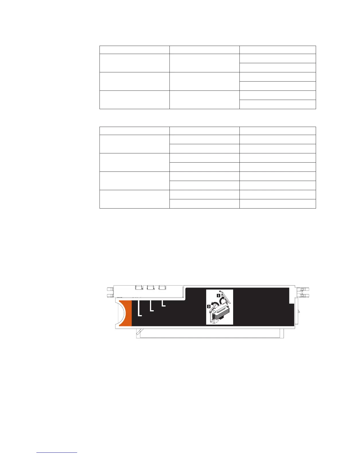
The following illustration shows the LEDs on the memory card:
Memory Hot-Swap Enabled
Memory Port Power
Error
Memory Hot-Swap Enabled LED: When this LED is lit, it indicates that
hot-swap memory is enabled.
Error LED: When this LED is lit, it indicates that a memory card or DIMM has
failed.
Memory Port Power LED: When this LED is off, it indicates that power is
removed from the port and that you can remove the memory card and replace a
failed DIMM. This LED will also turn off when the release levers are opened.
Note: Add odd numbered DIMMs to each available memory card first, then add
the even numbered pairs.
Chapter 4. Removing and replacing server components 39
 Loading...


