Related concepts
Installing features and replacing parts
Expansion units
Related tasks
Accessing the ASMI using a Web browser
Accessing the ASMI using an ASCII terminal
Serial uninterruptible power supply conversion cable
Place the rack-mounted system or expansion unit in the service position
Related reference
References
Related information
Adapters, Devices, and Cable Information for Multiple Bus Systems
Cabling your model 7037-A50 server
For a graphical representation of the slots and connectors, see the back view of the model.
Attention: This product is equipped with a three-wire power cable and plug for user safety. Use this
power cable with a properly grounded electrical outlet to avoid electrical shock.
To cable your server:
Before you begin
__ If you have hardware features that are not installed, install them now. For instructions, see Installing features
and replacing parts.
Connecting the power cords
__ Connect the power supply of your system to a power source.
Connecting the external cables
__ Connect a TTY terminal or terminal emulator to a serial port (T4 or T5), or connect a display monitor to an
optional graphics adapter in one of the PCI slots (P1-C5 through P1-C9).
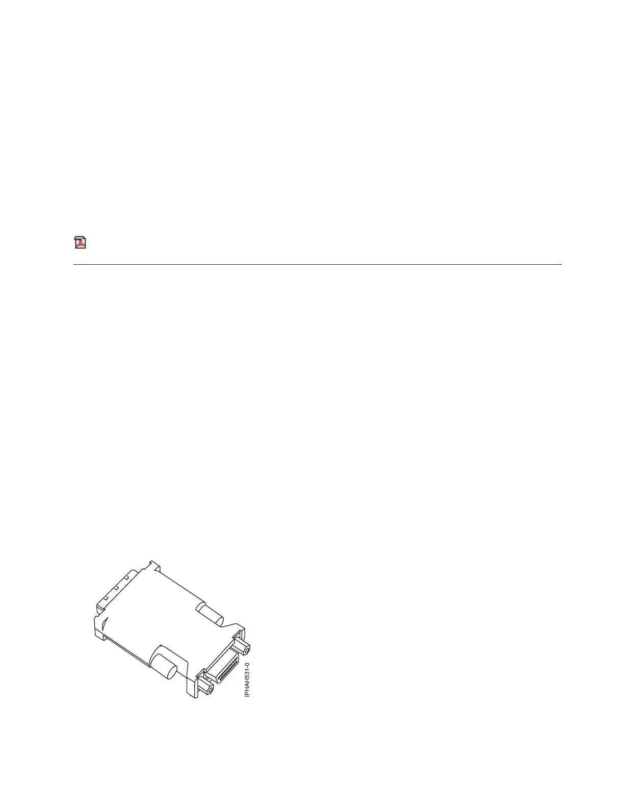
Tip: Some graphics adapters require a DVI-I to VGA converter. If you are using one of these graphics adapters,
attach the supplied converter (04N7533) to your monitor cable before connecting to the graphics adapter.
Figure 5. DVI-I to VGA converter
__ Connect a keyboard and mouse to the rear USB ports (T6 and T7), or connect a keyboard and mouse to the front
USB ports (T1 and T2).
__ If you want to connect the system with your network, connect a network cable to one of the Ethernet ports (T8
or T9).
Cabling your server 215
 Loading...