Chapter 4. Continuous availability and manageability 119
Service labels
Service providers use these labels to assist them in performing maintenance actions. Service
labels are found in various formats and positions, and are intended to transmit readily
available information to the servicer during the repair process. The following list details
several of these service labels and the purpose of each:
Location diagrams are strategically located on the system hardware, relating information
regarding the placement of hardware components. Location diagrams might include
location codes, drawings of physical locations, concurrent maintenance status, or other
data pertinent to a repair. Location diagrams are especially useful when multiple
components are installed, such as DIMMs, CPUs, processor books, fans, adapter cards,
LEDs, and power supplies.
The remove or replace procedure labels contain procedures often found on a cover of the
system or in other spots accessible to the servicer. These labels provide systematic
procedures (including diagrams) detailing how to remove and replace certain serviceable
hardware components.
Numbered arrows are used to indicate the order of operation and the serviceability
direction of components. Certain serviceable parts (such as latches, levers, and touch
points) must be pulled or pushed in a certain direction and certain order for the
mechanical mechanisms to engage or disengage. Arrows generally improve the ease of
serviceability.
The front panel
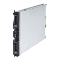
The front panel LEDs on the PS700, PS701, and PS702 blades indicate power status, error
and informational states, disk and network activity, and physical location within a BladeCenter
chassis.
Concurrent maintenance
The BladeCenter supporting infrastructure is designed with the understanding that certain
components have higher intrinsic failure rates than others. The movement of fans, and power
supplies make them more susceptible to wearing down or burning out. Other devices (such as
I/O modules) might begin to experience wear on mechanical connectors from repeated
plugging and unplugging for example, or other unexpected failure. For this reason, these
devices are designed to be concurrently maintainable when properly configured.
Live Partition Mobility (LPM) provides the ability to move workload off the PS700, PS701, and
PS702 blades allowing uninterrupted service when the blade or failed blade component is
replaced. The use of LPM would also be used to update the blade firmware without disrupting
operations.
Firmware updates
In a BladeCenter/Blade environment there are multiple areas to consider when looking at
firmware updates. In most cases, BladeCenter and infrastructure components can be
updated concurrently without disrupting blade operations.
POWER processor-based blades require a supported operating system running on the blade
to update the system firmware. Starting with the POWER6 generation blades and continuing
with the POWER7-based blades, LPM can be used to avoid the disruptive nature of blade
firmware updates. Firmware updates can provide fixes to previous versions and can enable
new functions. Blade system firmware typically has a prerequisite AMM firmware level.
A regular program of reviewing current firmware levels of the BladeCenter components and
the blades should be in place to ensure the best availability.

 Loading...


