Serial Console
Use this connection to configure and manage the BladeCenter components
through the advanced management module command-line interface (CLI).
For example, you can connect a notebook computer to the serial connector
and use a terminal emulator program to configure the IP addresses, user
accounts and other settings.
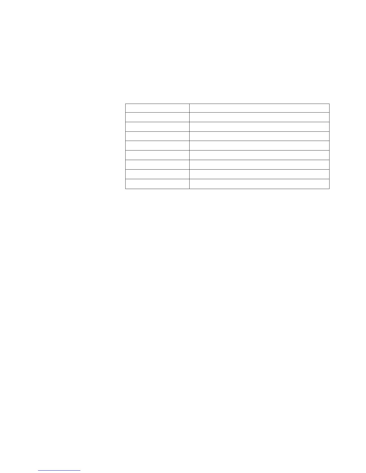
The serial pinout for the advanced management module is an EIA-561, as
shown in the following table:
Contact (pin number) Signal name
1 DSR (Data set ready)
2 DCD (Data carrier detect)
3 DTR (Data terminal ready)
4 GND (Ground)
5 Receive (RX)
6 Transmit (TX)
7 CTS (Clear to send)
8 RTS (Request to send)
Video Use this connector to connect a compatible SVGA or VGA video monitor to
the BladeCenter S system.
Ethernet
Use this connector to connect the BladeCenter S system to a the
management station, either through an Ethernet cable or on the network.
USB connectors
Use these connectors to connect a mouse and keyboard (or other USB
devices). Unlike the USB connectors on the media tray, these connectors are
shared by the blade servers through the BladeCenter Keyboard, Video,
Mouse (KVM) interface. The KVM interface owns these ports.
Note: If you connect a USB storage device to these connectors, the blade
server has ownership of the media tray and can access the device. To
switch ownership of the media tray to a specific blade server, press the
CD
button on that blade server.
Serial pass-thru module
The serial pass-thru module has six serial ports that you can use to directly attach
a four-wire serial RJ-45 connector to each of the blade servers in the BladeCenter S
chassis. If you use the serial pass-thru module, it must be installed in the serial
pass-thru module bay.
Note: See the documentation for the blade server that you are using to ensure that
it supports this type of serial access.
The connectors are numbered 1 through 6, from top to bottom, and correspond to
blade servers in blade server bays 1 through 6.
Chapter 1. Introduction 17
 Loading...