Powering on the system
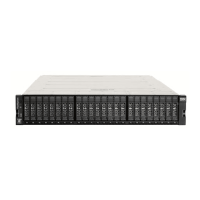
After you install all hardware components, you must power on the system and check its status. Each control enclosure has two power
supply units (PSUs). To provide redundancy in a power failure, connect the power cords to separate power circuits.
Attention: Do not power on the system with any open drive bays or host interface adapter slots. Open bays or PCIe slots
disrupt the internal air flow, causing the drives to receive insufcient cooling. Filler panels must be installed in all empty
drive bays and PCIe slots.
1. Ensure that the circuit breakers or switches of the power sources are turned on.
2. Ensure that each power cable is secured to each PSU on the back of the node. To do so, route each power cable through the retainer.
The cable retainer has a curved opening that faces the rear of the PSU. After you plug the power cable in to the PSU, slip the power cable
behind the retainer. Pull the cable back into the retainer opening to secure it. Then, route each power cable through the cable retainer.
For PSU 1, hook the power cable underneath the cable retainer so the cable can extend to the left.
For PSU 2, make a loop to secure the cable under the retainer and extend the power cable to the right side of
the node.
To remove a power cable, push the cable forward to unhook it from the cable retainer. Then, unplug the cable
from the PSU.
3. Connect the PSUs of the control enclosure and each expansion enclosure to their power sources.
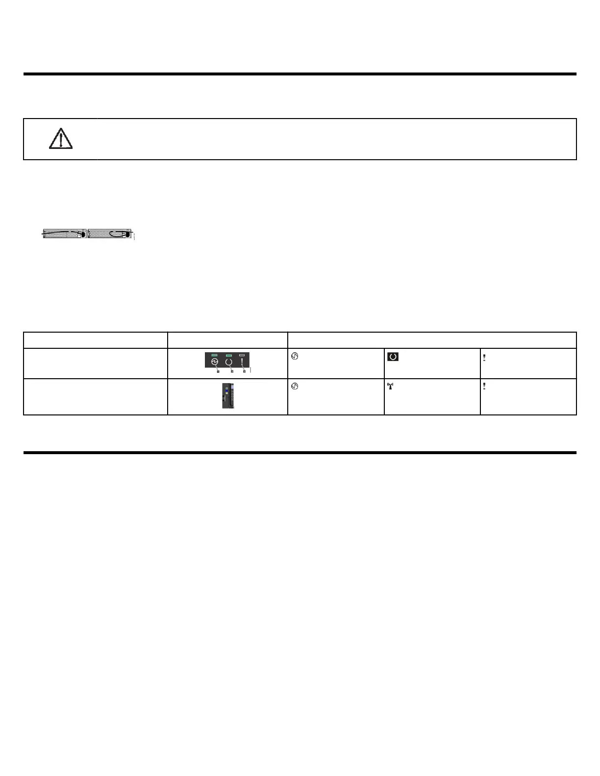
4. Check the status LED indicators to verify the status of the enclosure. The control enclosure is ready and running without critical errors
when the LEDs indicate the following status.
Location
LEDs Indicator Status
Back of each node canister (and 2U
expansion enclosures, if applicable)
Power LED is on (1).
Status LED is blinking
(2).
Fault LED is off (3).
Front of the control enclosure, left end
cap
Node operational LED
is on.
Identify node LED is
off (default).
Node fault LED is off.
Initializing the system
FlashSystem 5015 systems contain one I/O group (control enclosure). the FlashSystem 5035 systems can contain two I/O groups (two
control enclosures). To set up and initialize a new system, complete the following procedure and run the initialization tool.
Before you begin
• Ensure that a supported browser is installed on a notebook computer.
– Browser security features might prompt you to accept the self-signed certicate that the system issues.
– You might need to remove old certicates that are stored in the browser before it accepts the request.
– The web browser might display a warning about a potential security risk. It is safe to accept the risk and continue.
– See Browser considerations on page 11 for more information.
• Ensure that an Ethernet cable is available to connect the notebook computer to the technician port.
– After the technician port physical connection is completed (that is, connected both ends), it can take up to 45 seconds before the
port is fully able to process requests. Submitting requests before this interval might result in 404 error responses.
– Do not connect the technician port to a switch. If a switch is detected, the technician port connection might shut down, causing a 746
node error.
– See Ethernet cable standards on page 2 for more information.
Note:
If you are unable to connect to the system through the technician port, you can use the service assistant tool or the service
CLI to initialize the system. To do so, complete the following steps.
Procedure
1. Congure an Ethernet port on the notebook computer to enable Dynamic Host Conguration Protocol (DHCP) conguration of its IP
address and DNS settings. If you do not have DHCP, use the following information to manually congure the notebook computer.
9