Static IPv4 Address Subnet Mask Gateway DNS
192.168.0.2 255.255.255.0 192.168.0.1 192.168.0.1
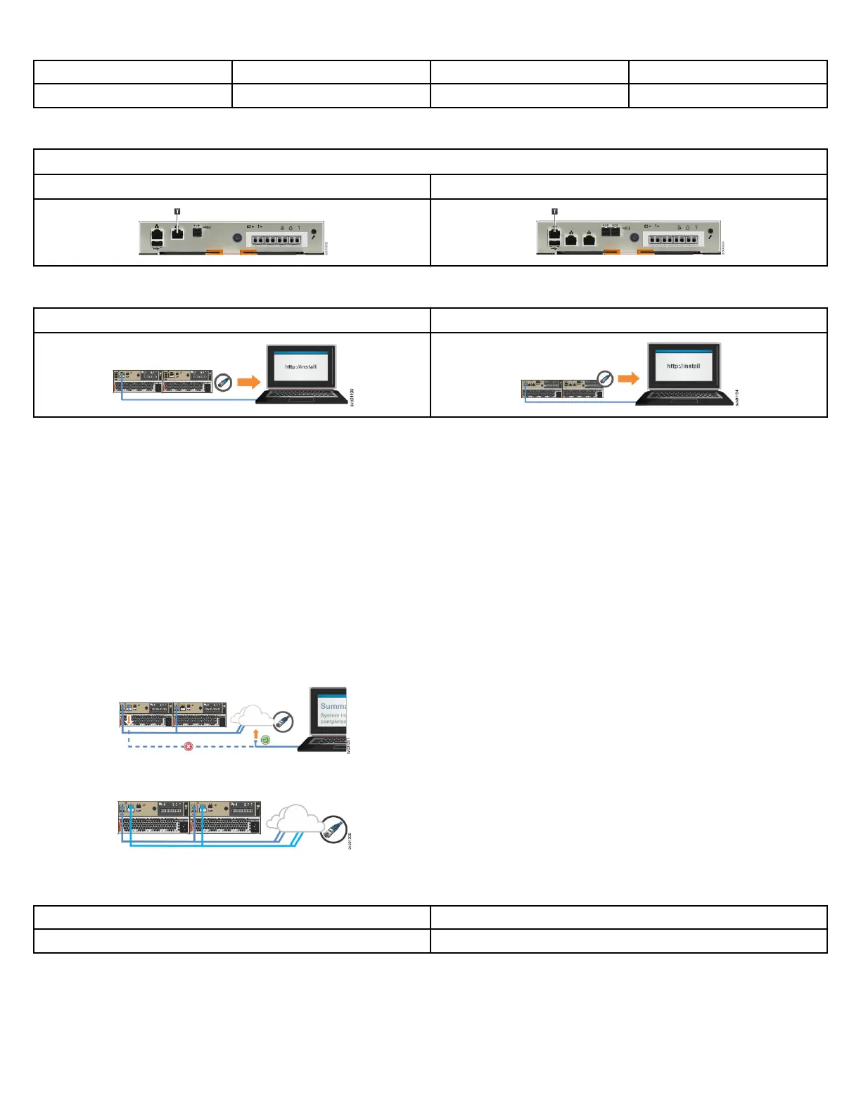
2. Locate the Ethernet port that is labeled T on the rear of the node canister. On FlashSystem 5015 systems, Ethernet port 2 also serves as
the technician port. the FlashSystem 5035 systems have a dedicated technician port.
Table 1: Location of the technician port on a node canister
FlashSystem 5015 the FlashSystem 5035
3. Connect an Ethernet cable between the port of the notebook computer and the technician port. The cable must be long enough to
connect easily to the computer.
FlashSystem 5015 the FlashSystem 5035
After the connection is made, the system automatically congures the IP and DNS settings for the notebook computer, if DHCP is
available. If it is not available, the system uses the values that you provided in step 1 on page 9.
4. After the Ethernet port of the notebook computer is connected, open a supported browser and go to address http://install. The
browser is automatically directed to the initialization tool.
If you do not have DCHP, open a supported browser and go to static IP address 192.168.0.1.
5. Follow the instructions in the initialization tool to congure the system with a name and management IP address.
Use the information that you provided in Management and service address worksheet on page 3.
6. If you experience a problem during the process due to a change in system states, wait 5 - 10 seconds. Then, either reopen the SSH
connection or reload the service assistant.
7. After you complete the initialization process, disconnect the cable between the notebook computer and the technician port.
• On FlashSystem 5015 systems, continue to step 8 on page 10.
• On the FlashSystem 5035 systems, go to step 10 on page 10.
8. On FlashSystem 5015 systems, connect the notebook computer to the network.
Ethernet port 1 remains connected to the network, as shown. Ethernet port
2 no longer acts as the technician port.
9. Optional: On FlashSystem 5015 systems, connect onboard Ethernet port 2 to the network.
After the system initializes, the technician port is automatically disabled.
Ethernet port 2 can then be connected to the Ethernet switch.
10.Enter the management IP address in a web browser to access the management GUI for the rst time.
a) Log in with the following credentials to start the initial setup process.
User ID
Password
superuser passw0rd
Using an alternative method to initialize the node
11.If you are unable to connect to the system through the technician port, you can use the service assistant tool or the service CLI to
initialize the system. To do so, complete the following steps.
a. Access the command line by using the credentials that are listed in Step 10 on page 10.
10