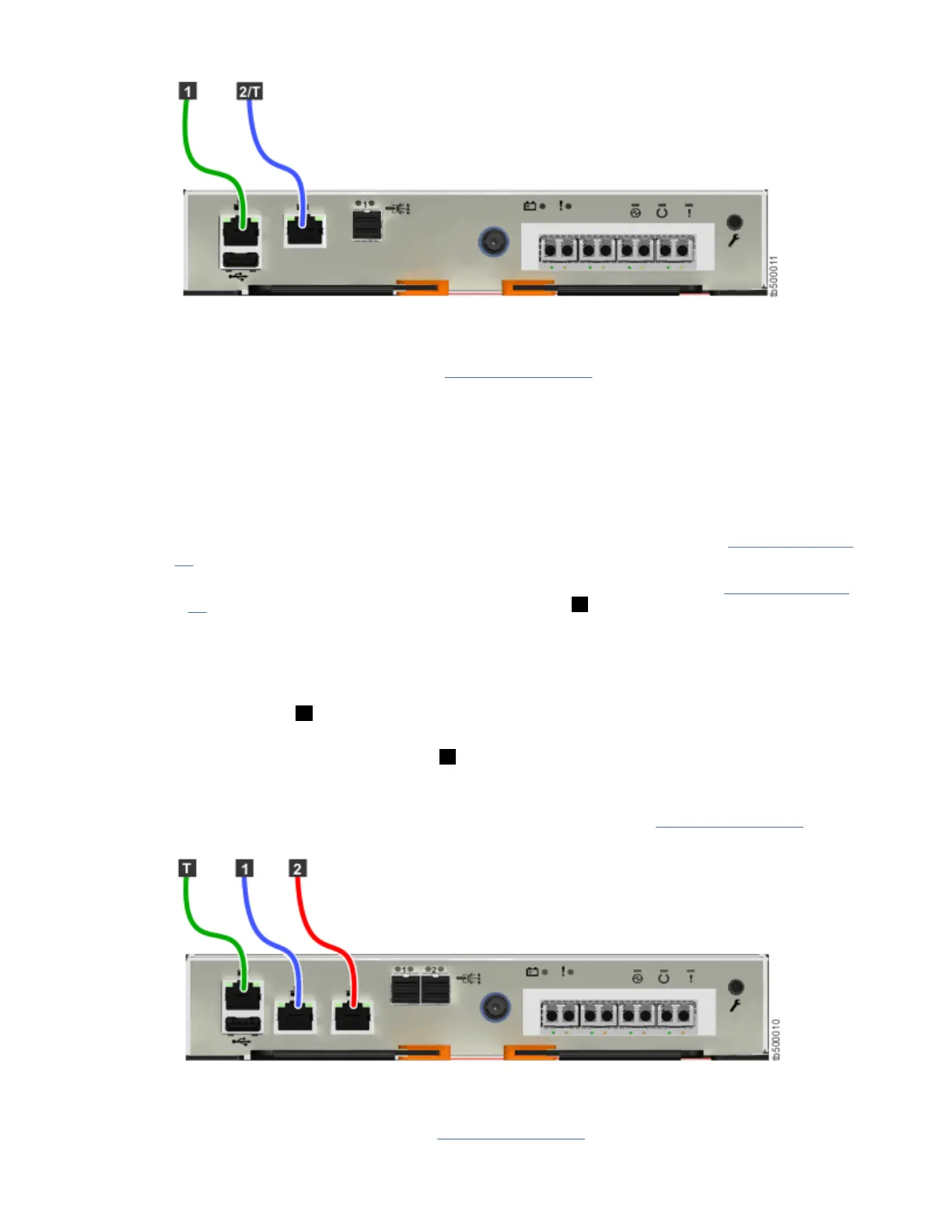
Figure 63. Connecting the Ethernet cables to a FlashSystem 5010 system
c) Optional: Connect Ethernet port 2 of each node canister in the system to a second IP network, as
shown by the blue cable connection in Figure 63 on page 65. This second port can be used to
provide a redundant connection to the system management interfaces; it can also be used for iSCSI
connectivity to the system by hosts on the network.
Note: On FlashSystem 5010 systems, the second Ethernet port is also used as the technician port.
Do not connect Ethernet port 2 to the SAN until the management GUI setup wizard completes on
each system and the cluster is created. If you have to service your system, disconnect port 2 from
the SAN before you enable port 2 to be the technician port again.
2. If you have a FlashSystem 5030 system, complete the following steps.
a) Identify the location and function of the Ethernet ports on your system; refer to Figure 64 on page
65.
• The technician port should only be used to initialize or service the system. In Figure 64 on page
65, the technician port is identied by the green cable ( T ).
Note: Never use the technician port to provide an Ethernet connection to the system. Do not
connect the Ethernet technician port to a network switch. The technician port must only be
directly connected to a personal computer when initializing a system or servicing a node.
• Ethernet port 1 can be used to provide Ethernet connections. In the gure, port 1 is identied by
the blue cable ( 1 ).
• Ethernet port 2 can optionally be used to provide additional Ethernet connections. In the gure,
port 2 is identied by the red cable ( 2 ). Port 2 can also be used for iSCSI connectivity or IP
replication.
b) Connect Ethernet port 1 of each FlashSystem 5030 node canister in the system to the IP network
that will provide a connection to the system management interfaces. Figure 64 on page 65 shows
the port locations and Ethernet cabling on a FlashSystem 5030 node canister.
Figure 64. Connecting the Ethernet cables to a FlashSystem 5030 system
c) Optional: Connect Ethernet port 2 of each node canister in the system to a second IP network, as
shown by the red cable connection in Figure 64 on page 65. Port 2 can provide a redundant
Chapter 4. Installing the system hardware
65