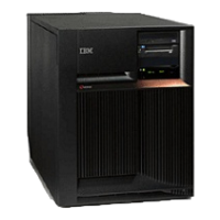
5. Pull the side fasteners to release the media tray from the system frame.
6. Remove the media unit and tray from the frame by sliding it forward.
7. Reverse these steps to install the new device.
Notes:
v If you need to remove a tape from the old tape unit, see Tape cartridge - Manual removal.
v If you need to remove a optical media, go to Optical media - Manual removal.
v If the replacement device is located in location D07, address jumpers are required. See Removable
media address jumper positions.
This ends the procedure.
Models 270, 800, and 810 - System unit backplane - MB1
For use by authorized service providers.
Use this procedure to remove or replace the system unit backplane in Models 270, 800, and 810.
If you are working on a Model 270, 800, or 810 that is housed in an FC 0551 frame, note that the upper
and lower system units are placed on rails in the frame. Follow these instructions and access the internal
parts by opening the front cover, and sliding the system unit out on its rails.
To remove or replace the system unit backplane - MB1:
1. Power off the system. See Power on/off the system and logical partitions.
2. Unplug the power cord from the back of the system unit. On Models 270, 800, and 810 with a system
unit expansion attached, disconnect both the system line cord and the expansion unit line cord.
3. Remove the left side cover. See Models 270, 800, and 810 - Covers.
4. Remove the PCI cards. See Models 270, 800, and 810 - Cards (dedicated). Note the locations to aid
in replacing them correctly.
5. Remove the lower and center cardboard. The center piece of cardboard is attached to the long PCI
support with one retaining screw. The cardboard that separates the air moving devices does not need
to be removed.
6. Remove all cables.
7. Remove the screws holding the backplane to the frame.
8. Remove the backplane assembly.
9. Install the new part by reversing the procedure.
10. Connect the power cord to the box and connect to AC.
11. Set the configuration ID:
a. Select function 07 on the system control panel, and press Enter. (07** will be displayed).
b. Use the arrow keys to increment/decrement to sub-function A9. (07A9 will be displayed). Press
Enter. (07A9 00 will be displayed).
c. Use the arrow keys to increment/decrement to the frame address of the box from which you just
replaced the backplane—usually 01 for the system unit (07nn will be displayed, where nn is the
frame address). Press Enter. (07nn 00 will be displayed).
d. Find the correct configuration ID from the following list:
v For Model 270:
– 91 :Model 270 with CCIN 2249, 224A, 25B9, 25BA and without FC 7104, (without removable
processor)
– 92: Model 270 with processor CCIN 24A0, 24A2, 25BD and without FC 7104, (with
removable processor)
– 95: Model 270 with CCIN 2249, 224A, 25B9, 25BA and with FC 7104, (without removable
processor)
Analyze hardware problems 15
 Loading...


