8. After replacing a part, go to Verify the repair.
This ends the procedure.
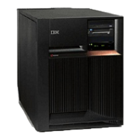
Model 825 - Control panel - NB1
For use by authorized service providers.
Use this procedure to remove or replace the control panel - NB1 in a Model 825.
Attention: The control panel is sensitive to electrostatic discharge. See Work with electrostatic
discharge-sensitive parts.
To remove or replace the control panel - NB1:
1. Power off the system See Power on/off the system and logical partitions.
2. Disconnect the ac power cord from the system unit, or on systems with dual line cords, disconnect
both of the ac power cords.
3. Open the front cover. See Model 825 - Covers.
4. Pull on the two knobs to release the control panel assembly.
5. Slide the panel partially out of the frame.
6. Are you here to exchange the processor capacity card?
v No: Continue with the next step.
v Yes: Perform the following:
a. Pull the processor capacity card off the control panel card, and put the new one in place. Note
the position and orientation of the card. See Control panel assembly - Models 820 and 825.
b. Reinstall the control panel card by reversing the procedure to this point.
c. Perform a manual IPL to DST. If the system stops at the System Password Required screen,
DO NOT BYPASS. Contact your next level of support to obtain a System Password and enter it
on this screen.
Note: DST/SST options to activate POD will not be visible if the system password has been
bypassed.
d. If you are replacing a processor capacity card that was associated with processor-on-demand
(POD) processor features, perform the following (otherwise go to step 6e (See page 33)):
1) Contact your second level of support to determine if a POD activation code is required to
reset previously activated on-demand processors.
2) If necessary, a new POD activation code will need to be generated and then entered at the
server.
3) After entering a POD activation code, 30 minutes should elapse before an IPL is performed
to ensure the POD activation code has been saved.
Attention: The POD activation code or codes must be entered within 48 hours or an SRC
A6XX 47XX will be posted in the panel requiring an IPL and, or LPAR configuration
adjustments.
e. Go to Verify the repair.
This
ends the procedure.
7. Disconnect the cables that are attached to the backside of the control panel.
8. Remove the control panel from the frame.
9. Remove the control panel cover and the processor capacity card. Note the position and orientation of
the card. See Control panel assembly - Models 820 and 825.
10. Install the processor capacity card into the new panel and replace the cover.
11. Reverse the above procedure to install the panel.
Note:
When a control panel with keystick is replaced, discard the new keys that come with the panel
and reuse the original keys.
Analyze hardware problems 33
 Loading...


