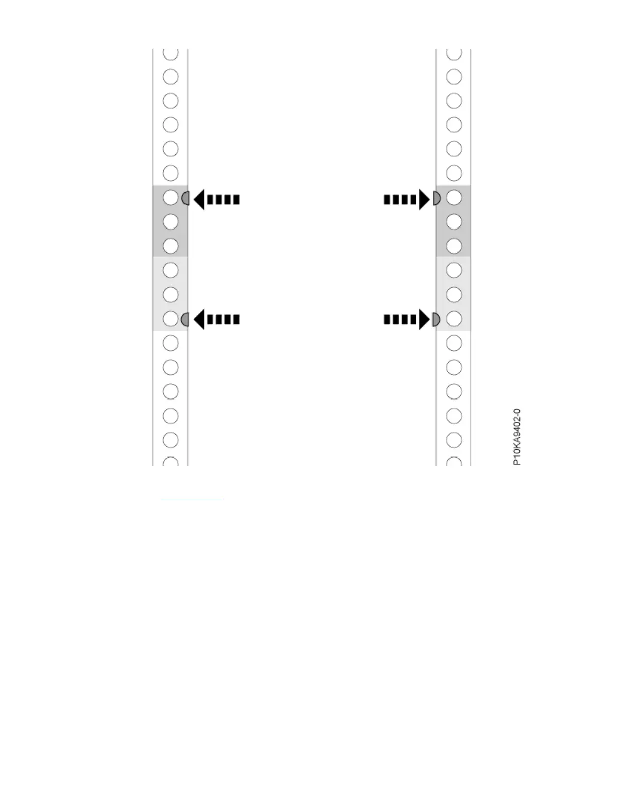
Figure 3. Marking the rack flange holes
6. Repeat step “5” on page 4 for the corresponding holes located on the left side of the rack. In later
steps you will be installing the rails in between these marked rack flange holes.
The following graphic shows the top location that you marked (1) and the lowest location that you
marked (2). The rail pins (3) and (4) will extend through the rack flange and, in later steps, you will
install a screw into each threaded hole on the rail (5) and (6).
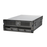
Installing the IBM Power S1012 (9028-21B)
5



 To Next Page