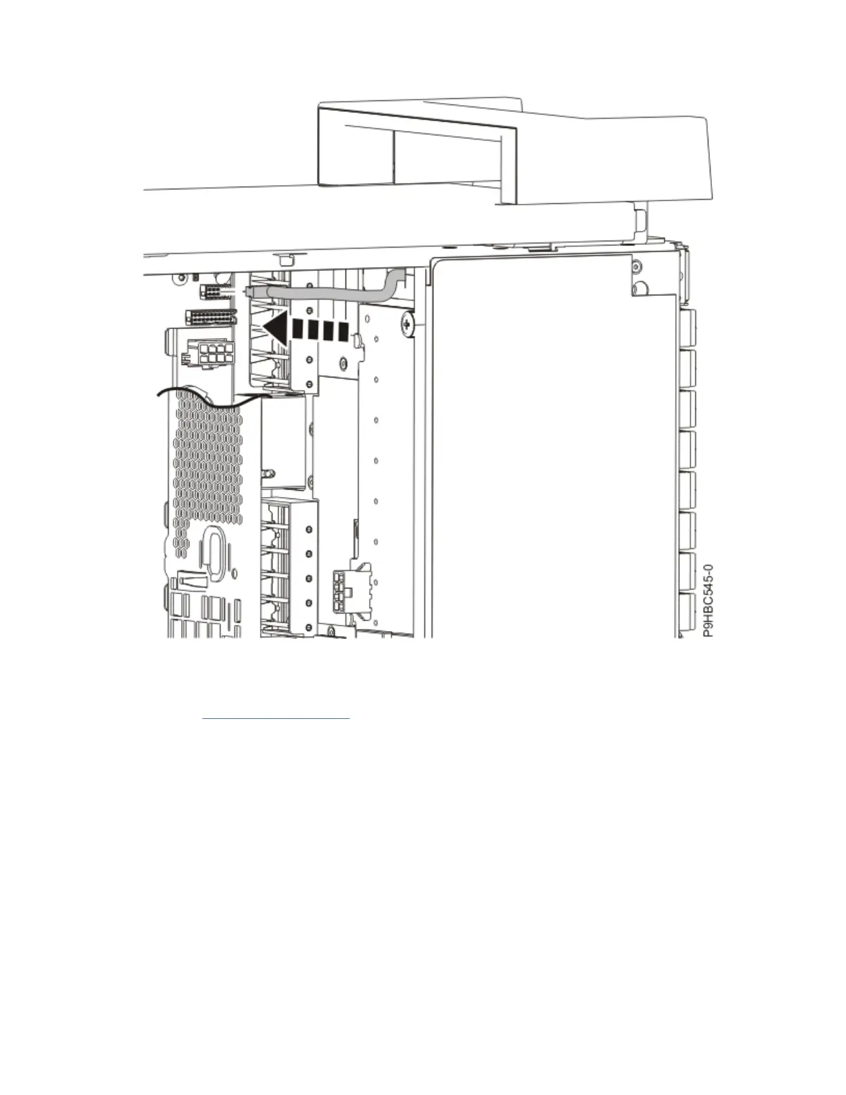
Figure 124. Connecting the control panel display cable to the system backplane for a stand-alone
system
7. For a rack-mounted system, attach the control panel display holder to the system with two screws as
shown in Figure 125 on page 130.
Control panel cables for the 9009-41A, 9009-42A, or 9223-42H
129
 Loading...


