Figure 115. Removing the control panel display cable from the housing for a rack-mounted system
Replacing the control panel display cable in the 9009-41A, 9009-42A, or 9223-42H
system
To replace a control panel display cable, complete the steps in this procedure.
Procedure
1. Ensure that you have the electrostatic discharge (ESD) wrist strap on and that the ESD clip is plugged
into a ground jack or connected to an unpainted metal surface. If not, do so now.
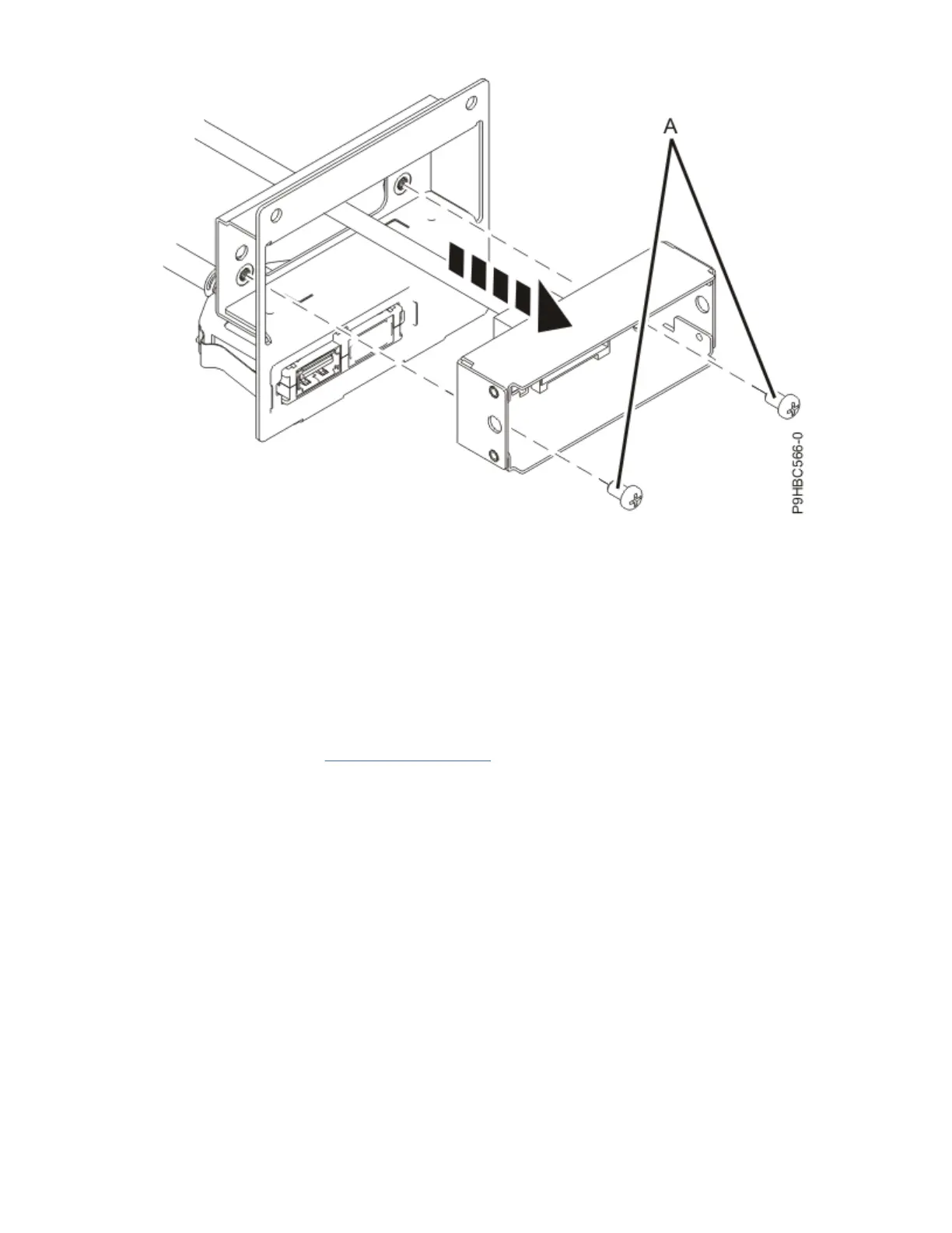
2. For the rack-mounted system, install the control panel display cable to the housing using the two
screws (A) as shown in Figure 116 on page 121
.
120
Power Systems: Power Systems: Control panel
 Loading...


