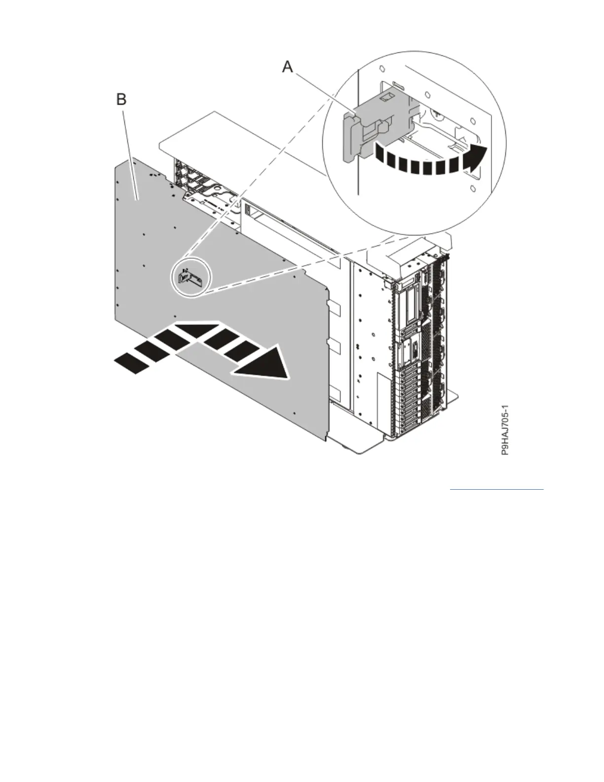
Figure 27. Installing the service access cover
3. For a rack-mounted system, unlock the blue rail safety latches (A) as shown in Figure 28 on page 30
by pushing them inward.
Ensure that the cable management arms can move freely. Ensure that the cables at the rear of the
unit do not catch or bind as you push the unit into the operating position.
Control panel and control panel display for the 9009-41A, 9009-42A, or 9223-42H
29
 Loading...


