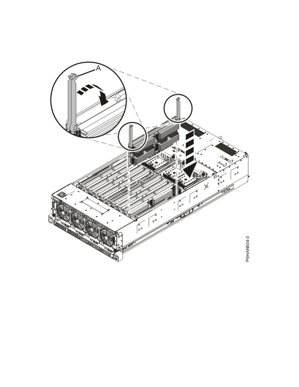
a) Ensure the release latches (A) are fully open to a 90 degree angle as shown in the following gure.
b) Align the memory riser with the connector.
c) Press the memory riser rmly into the connector.
d) Rotate the release latches into the closed position, and press the release latches down to ensure
that the memory riser is fully seated into the connector.
Figure 28. Inserting a memory riser
3. Replace the service access cover.
a) Lower the cover (A) onto the system unit. Ensure that the cover alignment pins (C) on each side of
the cover t into the matching slots in the chassis.
b) Slide the cover (A) onto the system unit. Ensure that the tabs (D) tuck under the mesh along the
front opening of the chassis.
c) Close the release latches (B) by pushing it in the direction that is shown in the following gure.
Memory modules for the 9040-MR9
39