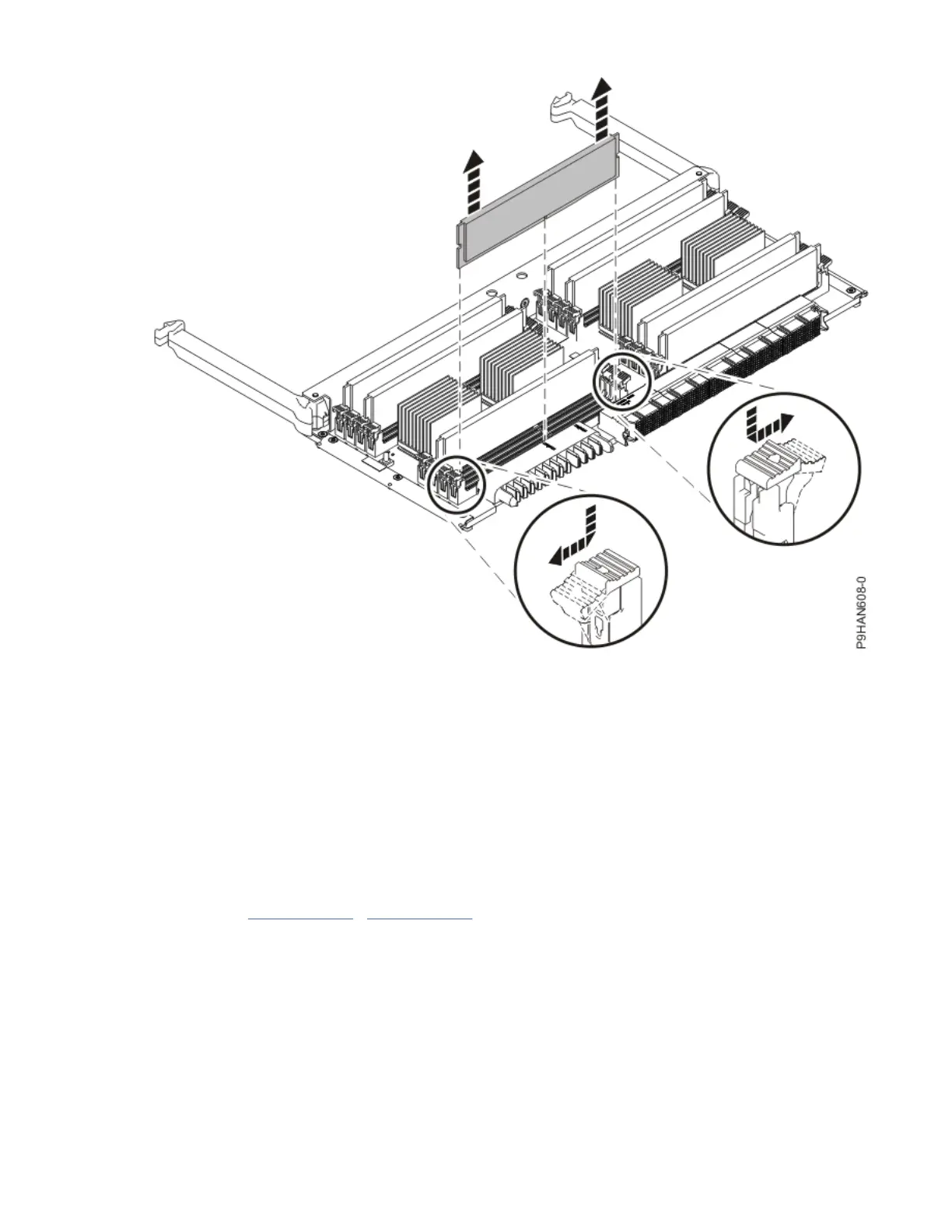
Figure 27. Removing a memory module
3. Hold the memory module by the edges and pull it out of the system.
4. If the removed part is used again, place the part on an electrostatic discharge (ESD) mat.
5. Insert a memory module ller.
Note: The memory module slots must contain either a memory module or a ller to ensure proper
cooling.
To insert the memory module ller, complete the following steps:
a) Ensure that the locking tabs are open.
b) Hold the memory module ller by the edges and press it rmly into the slot until the locking tabs
lock into place.
6. Repeat steps “2” on page 37 - “5” on page 38 to remove the other memory modules.
Preparing the 9040-MR9 system for operation after permanently removing a memory
module
To prepare the system for operation after you permanently remove memory modules, complete the steps
in this procedure.
Procedure
1. Ensure that you have the electrostatic discharge (ESD) wrist strap on and that the ESD clip is plugged
into a ground jack or connected to an unpainted metal surface. If not, do so now.
2. To insert the memory riser, complete the following steps:
38
Power Systems: Power Systems: Memory