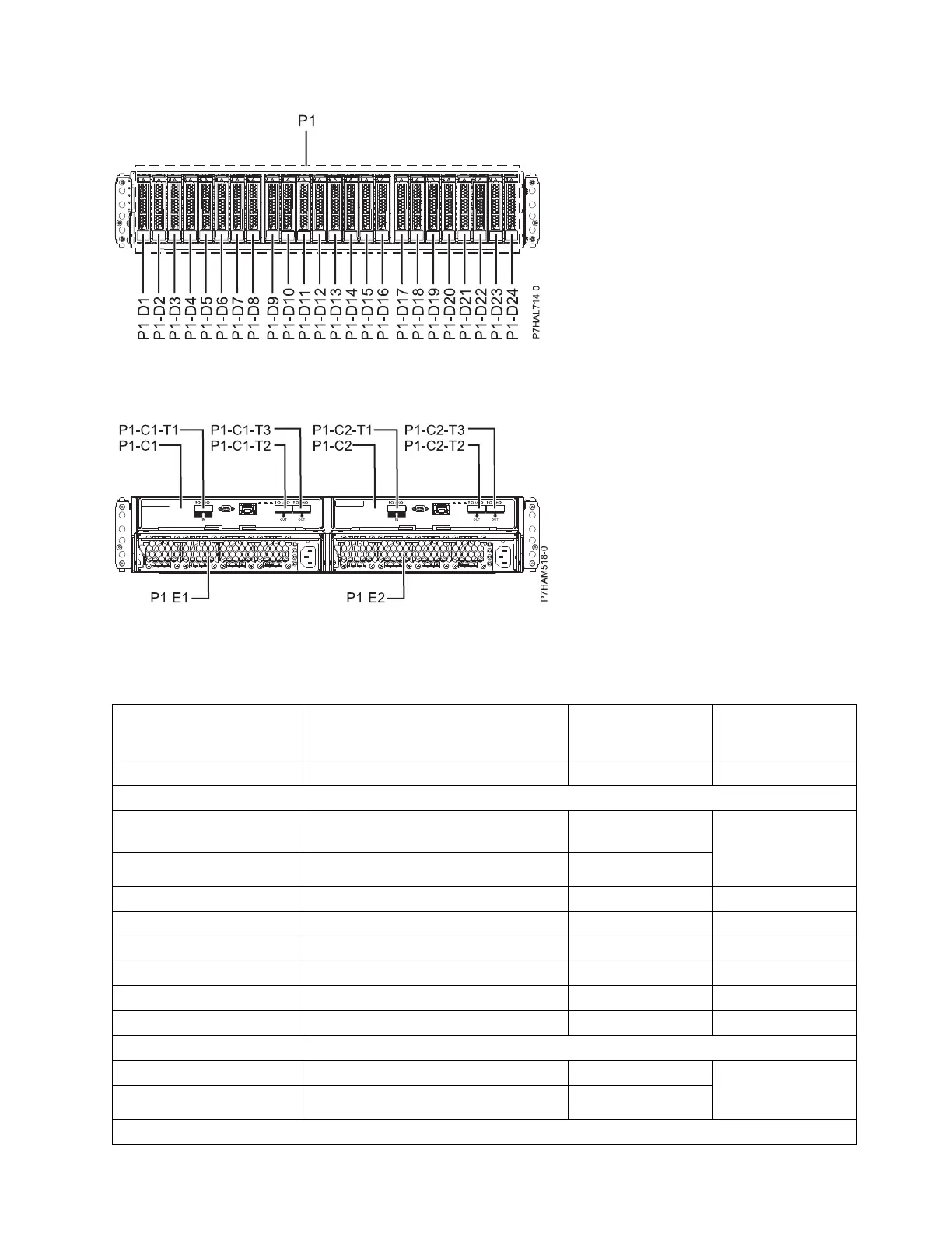
The following table provides location codes for parts that make up the server.
Table 50. FRU locations and failing components
Failing item name Physical location code Identify LED Failing item removal
and replacement
procedures
System unit Un
ESM
Event Services Manager
(ESM) A
Un-P1-C1 Yes See Removing and
installing an
enclosure services
manager.
ESM B Un-P1-C2 Yes
ESM A connector Un-P1-C1-T1
ESM A connector Un-P1-C1-T2
ESM A connector Un-P1-C1-T3
ESM B connector Un-P1-C2-T1
ESM B connector Un-P1-C2-T2
ESM B connector Un-P1-C2-T3
Power supplies
Power supply Un-P1-E1 Yes See Removing and
installing a power
supply.
Power supply Un-P1-E2 Yes
Midplane
Figure 60. Front view
Figure 61. Rear view
Finding parts, locations, and addresses 163

 Loading...