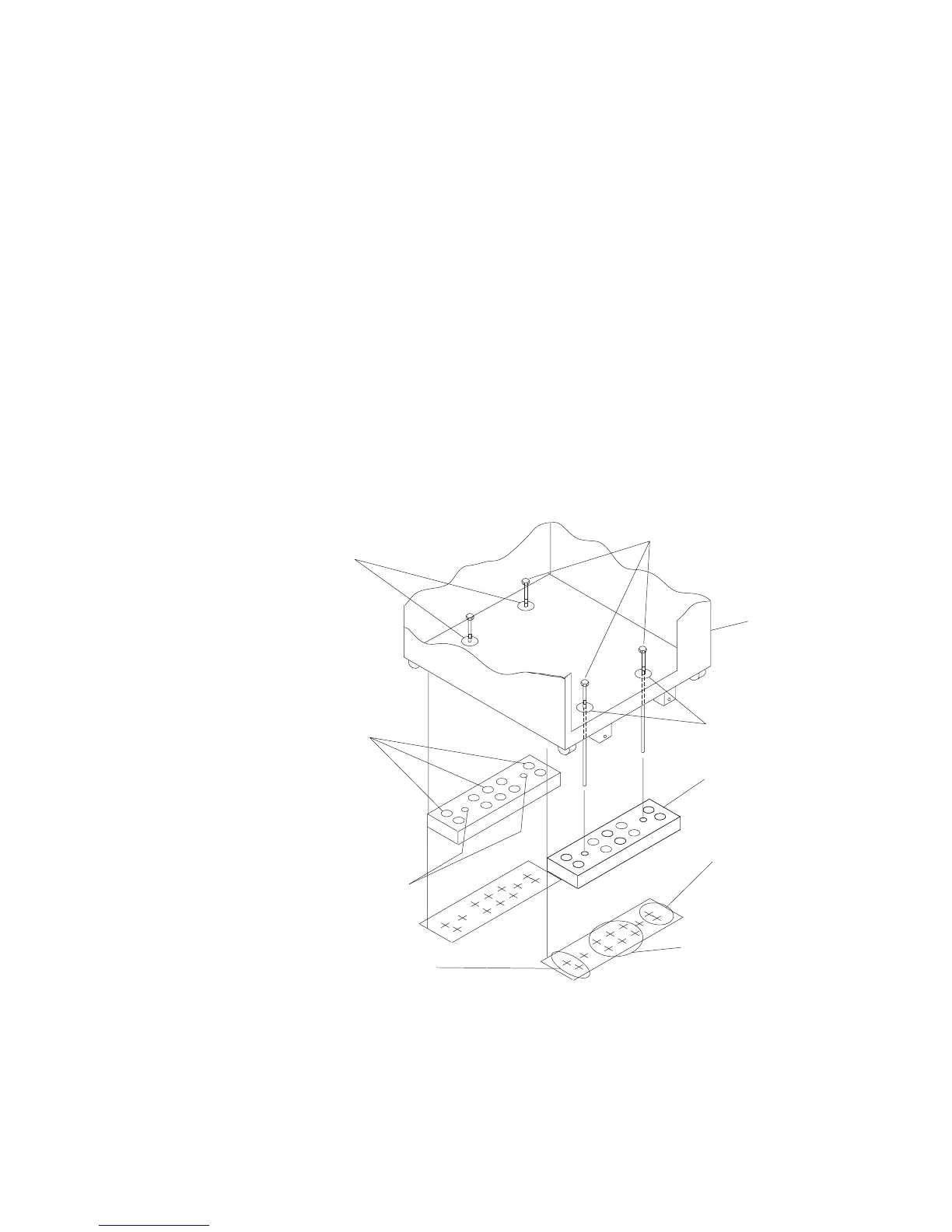
7. To access the holes in the mounting plates, raise the four leveling feet, and then
move the rack away from the mounting plates.
8. Mark the floor at the center of each hole in the mounting plate (including the
tapped holes).
9. Remove the two mounting plates from the marked locations.
10. At the marked location of the tapped mounting holes, drill two holes
approximately 1 inch deep to allow clearance for the ends of the two
rack-mounting bolts The ends of the rack-mounting bolts may protrude past the
thickness of the mounting plate.
Note: A minimum of three anchor bolts for each mounting plate must be used
to mount the plates to the concrete floor. Because some of the drilled
holes may be aligned with concrete reinforcement rods below the surface
of the concrete floor, some of the drilled holes may not be usable. For
each mounting plate, select at least three usable holes, two that are on
opposite sides and opposite ends of each other, and one hole at the
center.
Mounting Plate (2)
Location Marks
(Drill One of
TheseTwo Marks)
Holes for Anchor
Bolts (10)
Tapped Holes for
Rack Mounting Bolts
Mounting Holes
Mounting Holes
Rack Mounting Bolts
Front of
Rack
Location Marks (Drill One
of These Two Marks)
Location Marks (Drill
One of These Six Marks)
11. Drill one hole in each group of anchor bolt location marks as indicated on the
marked floor.
Chapter 2. System Installation 2-9
 Loading...


