Figures
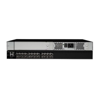
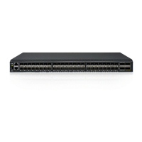
1. Port side view ............3
2. Non-port side of the switch .......4
3. Items in the slim rail rack mount kit ....10
4. Position the front bracket ........11
5. Position the switch in the cabinet .....12
6. Position the rear and front brackets ....12
7. Attach the rear bracket to the cabinet rail 13
8. Installing a 16 Gbps SFP+ with pull tab
(shown without cable attached) ......20
9. SFP+ with wire bail latch ........21
10. Installing a cable ...........21
11. Port side LEDs ...........26
12. Non-port side LEDs..........26
13. Intake airflow label ..........31
14. Switch power supply and fan assemblies on
the non-port side...........32
15. Removing the power supply and fan assembly 34
16. Location of battery holder........36
17. Identifying the origin of failure ......43
© Copyright IBM Corp. 2011, 2013 ix
||

 Loading...