Replacing the memory expansion module bezel
To confirm that the memory expansion module supports the bezel that you are
installing, see http://www.ibm.com/systems/info/x86servers/serverproven/
compat/us/.
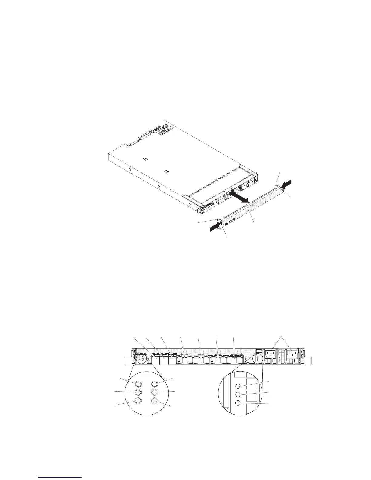
To replace the memory expansion module bezel, complete the following steps:
1. Read “Safety” on page v and “Installation guidelines” on page 38.
2. Align the bezel alignment tabs with the chassis and press the bezel onto the
chassis until it snaps into place.
Bezel
Alignment
tab
Alignment
tab
Release
tab
Release
tab
Connecting the memory expansion module cables
To cable the memory expansion module to the host server, see the QPI cable option
documentation and the EXA cable option documentation. Be sure to turn off the
host server before you connect any cables to or disconnect any cables from the
memory expansion module.
The following illustration shows the locations of the connectors on the rear of the
memory expansion module.
Power-on
LED
Locate
LED
System
error
LED
AC LED (green)
DC LED (green)
Power supply
fault (error) LED
QPI
port 1
Power
connectors
EXA port 1
LEDlink
EXA port 2
LEDlink
EXA port 3
LEDlink
EXA
port 1
EXA
port 2
EXA
port 3
QPI
port 2
QPI
port 3
QPI
port 4
92 IBM System x3850 X5 and x3950 X5 Types 7145, 7146, 7143, and 7191: Installation and User's Guide
 Loading...


