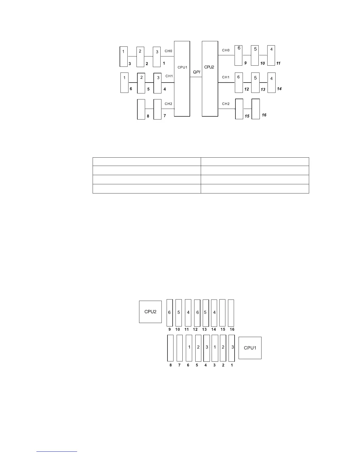
The following table lists the DIMM connectors on each memory channel.
Table 11. Connectors on each memory channel
Memory channel DIMM connectors
Channel 0 1, 2, 3, 9, 10, 11
Channel 1 4, 5, 6, 12, 13, 14
Channel 2 7, 8, 15, 16
The following illustration shows the memory connector layout that is associated with
each microprocessor. For example, DIMM connectors 9, 10, 11, 12, 13, 14, 15, and
16 (DIMM connectors are shown underneath the boxes) are associated with
microprocessor 2 socket (CPU2) and DIMM connectors 1, 2, 3, 4, 5, 6, 7, and 8 are
associated with microprocessor 1 socket (CPU1). The numbers within the boxes
indicate the installation sequence of the DIMM pairs. For example, the first DIMM
pair (indicated within the boxes by ones (1)) should be installed in DIMM connectors
3 and 6, which are associated with microprocessor 1 (CPU1).
Note: You can install DIMMs for microprocessor 2 as soon as you install
microprocessor 2; you do not have to wait until all of the DIMM connectors for
microprocessor 1 are filled.
Figure 1. Memory channel interface layout
Figure 2. Memory connectors associated with each microprocessor
84 System x3650 M2 Type 7947: Installation and User’s Guide

 Loading...


