Do you have a question about the IBO 3SDm and is the answer not in the manual?
Describes use for clean water and limitations on contaminants like sand and abrasive particles.
Instructions for connecting hydraulic and motor parts, tightening screws, and shaft coupling.
Specifies maximum borehole diameters for motor cooling and pump efficiency.
Ensuring sufficient water level above discharge port to prevent dry running damage.
Guidance on fixing supply cable and suspending pump to prevent sinking.
Rule for switching frequency of pump motor (max 30 times/hour) to prevent overload.
Mandatory active earthing and liability for lack of it.
Requirement for overcurrent circuit breaker and RCD not exceeding 30 mA.
Prohibition of use with damaged cables; checking voltage and selecting cable length.
Guidelines for extending cables, hermetic connection, and potential risks.
Generator power should be 3-5 times higher than the motor's rated current.
Correct sequence for connecting/disconnecting pump and generator to avoid motor burnout.
Instructions for storing the pump in a dry room on an even surface.
Disposal via selective waste systems and customer entitlement to return used equipment.
Possible causes: dry operation, overcurrent, or no power supply.
Causes: blocked suction, incorrect rotation, high resistance, low voltage, or low water level.
Causes: small hydrophoric tank, lack of air cushion, or narrow pressure switch differential.
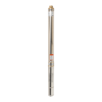
This document serves as an instruction manual for a range of deep-well pumps manufactured by VIBO, including models such as 3SDm, 3SD, 3ti, 3t2i, 3SKm, 4SKm, 4SCR, 4SD, 4SDm, 3.5"SCM, 3.5”SCR, 90MSC, 3”SQIBO, STING, DWP, 3”SCR, 4”ISP, 6"ISP, 4"ISPm, 4"SCR, OLA, 2,5"STm, and 3STm. It is crucial to read this manual thoroughly before operating the pump, as it contains vital safety information and operational guidelines. The manual is considered an integral part of the purchase and sale contract, and non-compliance with its instructions may void the warranty and lead to repair costs.
These deep-well pumps are designed for pumping clean water from bored deep water intakes. They can also be used to increase pressure in water systems by enclosing the aggregate in a hermetic jacket. Their primary applications include household water supply, irrigation, heat pump installations, and feeding water into industrial installations. The pumps are specifically engineered to handle clean water, meaning the pumped water must not contain any mechanical contamination.
A critical aspect of their function is the handling of sand. While some models offer increased resistance to sand, the manual explicitly states that pumping water with sand contamination significantly shortens the pump's lifespan. Wear and tear resulting from pumping sand are not covered under warranty, as it is considered operational wear. For most pumps, the maximum permissible sand content in the water is 5%. The manual warns that pumping water containing abrasive particles will lead to rapid wear and tear and eventual failure, incurring paid repair costs.
The pumps are not designed for pumping caustic, flammable, destructive, or explosive substances such as petrol, nitro, oil, foodstuffs, or salty water. Damage caused by pumping such liquids is not subject to warranty repair. The maximum temperature of the pumped water should not exceed 35°C. Furthermore, the pumps are not suitable for pumping water with excessive mineral content that could cause scale deposition on pumping elements, as this would lead to premature wear and tear and paid repairs. The pumps also cannot handle water containing oils or petroleum derivatives, which could damage rubber components, leading to leaks and motor failure, again resulting in paid repairs. Finally, the pumped water must be free of any long-fibrous contamination.
Installation: Prior to any installation work, the power supply must be disconnected, and measures must be taken to prevent accidental switch-on. Some pump models (3ti, 3t2i, 3SDm, 4SD, 4SDm, 4ISP, 4ISPm, 6ISP, 3STm) may be delivered in two parts: a hydraulic section and a motor. For these, the clamping screws protecting the cable strip, strainer, and clamping nuts with washers must be removed before assembly. The hydraulic element is then mounted onto the motor shaft, ensuring the splines align with the motor clutch by turning the shaft if necessary. Once correctly mounted, the hydraulic element is fully supported by the motor's top bearing body. The aggregate is then secured with screw nuts and washers, tightened crosswise, with a minimum tightening moment of 18 Nm for 4” motors. Failure to tighten screws accurately can lead to the motor "sinking" in the borehole. After installing the hydraulic element and routing the power cable, the strainer must be reinstalled and screwed before attaching the cable protection strip. Lowering the pump into the borehole without a surge protector can damage cable insulation, potentially causing pump failure or electrocution.
For specific pump models (SD, SDm, SCM, ISPm, ISP, STm), proper motor cooling is essential. The borehole diameter where these pumps operate must not exceed the values specified in a provided table, which are consistent with pump efficiency. Using the pump in a wider well can lead to motor overheating and failure. If the well diameter is wider than specified, the pump must be installed in a special jacket to ensure proper cooling. The pump should be installed in the well section above the filter, maintaining a minimum distance of 30 cm between the upper edge of the well filter and the bottom edge of the motor. Installing the pump closer to the bottom can lead to sand suction, accelerating wear of pumping elements, and if placed in sludge, it can cause motor overheating.
The pump must never operate "dry" without water, as this will cause device damage and necessitate paid repairs. To prevent dry operation, the pump should be installed at a depth where the lowest dynamic water level (measured during constant pumping with slow inflow) is at least 2 m above the discharge port. If the well's efficiency is insufficient for the pump, solutions include installing a valve on the pumping pipeline to constantly limit flow or using a security device that monitors the water mirror level and switches off power supply in case of dry operation hazard.
When lowering the pump, the supply cable must be secured to the supply pipe with plastic bands at intervals not exceeding 2 m. For significant installation depths, an unattached cable could break due to its weight. It is also recommended to suspend the pump on a steel line to prevent it from sinking if the delivery pipeline becomes unscrewed. A check valve, protecting against impacts from returning water, must be installed directly above the pump.
Electrical Connection: The electrical network powering the pump must comply with the data on the rating plate. The pump requires connection to a network with active earthing, and the yellow-green core of the connection cable is for earthing. The manufacturer is not liable for damages resulting from improper earthing. The powering network must include an overcurrent motor circuit breaker (e.g., M611) to protect the motor against overload. For maximum protection, the switch should be set to the maximum coil current specified on the rating plate. While the device can operate without this protection, the user will bear repair costs for overload-induced failures. The pump's powering installation must also be equipped with a residual current device with a rated making current (Aln) not exceeding 30 mA. The manufacturer disclaims liability for damages caused by supplying power without a proper switch.
It is strictly forbidden for people or animals to be in the water where the pump is operating. If cable insulation is damaged, pump use is prohibited, and the guarantor must be contacted for cable replacement. Mechanical damages are not covered by warranty. Using a pump with damaged cable insulation can lead to motor flooding or, in the worst case, electrocution. Before launching the pump, the voltage at the cable's end must be checked. Longer cables result in lower supply voltage, and admissible voltage drops for motors are ±6%. To prevent excessive voltage drop, the cable length must be appropriately selected based on power supply type (one or three-phase), motor power, and cable length, with a table provided for guidance.
Failure to follow cable selection instructions can lead to pump operation with low voltage and subsequent motor overload and failure. If the pump comes with a short cable, it can be extended by a person with adequate knowledge and experience, ideally a well fitter or the well purchase shop. Unprofessional cable connection and insulation can trigger residual-current devices, motor flooding, or electrocution. Cable extension for pumps with a launching cable box may require disassembly. Before disassembly, it's recommended to check the existing cable core connections and replicate them for the extension cable. Incorrect connections can cause motor or pump failure and reduced performance. It is advisable to have the guarantor or a well fitter perform power supply cable extensions.
Some pump types are delivered with a separate cable box containing a starting capacitor, overcurrent protection, and a switch. A diagram illustrates how to connect the power supply cable cores to the connecting strip in the box, with cores marked by tags or color.
Pump Matching with Power Generator: When using a power generator, its rated current should be 3 to 5 times higher than the pump motor's rated current due to the high starting current. When launching the pump with a generator, the pump must only be connected after the generator has started. Connecting the pump to a running generator can burn out the pump motor, leading to paid repairs. To switch off the pump, first disconnect the pump, then switch off the aggregate. Switching off the aggregate with the pump still connected can also burn out the motor, resulting in paid repairs.
Storage: After cleaning, the pump must be stored in a dry room. It is essential to ensure the pump is placed on an even surface along its entire length. Supporting the pump at only one or a few points can cause deflection and lead to failure.
Troubleshooting: The manual includes a troubleshooting section to address common operational problems:
Device Disposal: Used products must be disposed of as waste through selective waste collection systems organized by Communal Electric and Electronic Waste Collection Centres. Customers are entitled to return used equipment to the electric equipment distributor, free of charge, provided the returned device is of the proper type and fulfills the same function as a newly purchased device.
The pump motor is filled with ecological oil. In the event of motor failure, this oil could leak into the well, highlighting the importance of proper maintenance and timely repairs to prevent environmental contamination.
| Power | 0.37 kW |
|---|---|
| Voltage | 220-240 V |
| Pump Diameter | 3 inch |
| Outlet Size | 1 inch |
| Maximum Head | 32 m |
| Maximum Flow Rate | 3.6 m³/h |
| Outlet | 1 inch |
| Max Flow Rate | 3.6 m³/h |
| Max Head | 32 m |