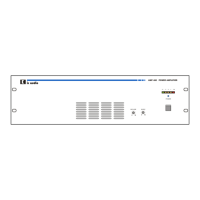
14. Connection of callstations
Insert RJ45 cable to paging station terminal and callstation unit.
Each callstation include one MT-PM-06 and 4 MT-PM-K12 units, it can control up to 54
Zones. It can connect 6 callstations.
Each callstation should be assigned fix ID to identify the data communication address
between MT-AMP 1000 and callstations.
All of the priority and chime mode setting are defined by the 1st callstation.
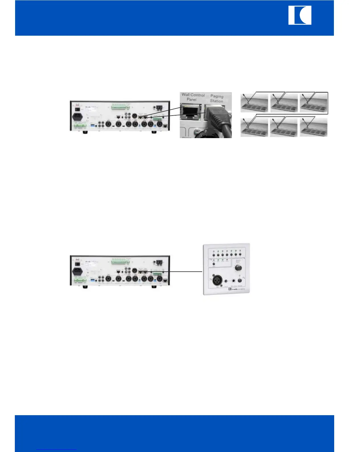
With RJ45 cable to connect wall control panel to the MT-AMP 1000 by wall control panel terminal (50).
Press the activate push switch of MT-WCP-6 and push the select switch of MT-AMP 1000
to select remote LED ON.
b. The wall panel can control the MT-AMP 1000.
c. The MT-WC-6 is able to control the Z1 to Z6 output.
d. It is also can select music source and AUX1, AUX2, AUX3 by select key.
e. The user can give speech through microphone XLR input.
f. It can insert external LINE in signal to mix with microphone signal of wall panel.
Note:
If the remote LED of MT-AMP 1000 is not selected, the wall panel will be standby state.
15. Wall control panel
MT-AMP 1000
ic audio GmbH
Boehringerstraße 14a; D-68307 Mannheim; Germany
Fon: + 49(0) 621 / 77096-0; Fax: + 49(0) 621 / 77096-26
E-Mail: info@ic-audio.com; www.ic-audio.com
EN
19
ic audio
 Loading...