Do you have a question about the Ice-O-Matic CIM Series and is the answer not in the manual?
Warnings and cautions regarding electrical safety and protective equipment.
Explains the sequence of operations during the freeze cycle.
Details the process of compressor start-up and hot gas valve operation.
Explains the energizing of components during the harvest cycle.
Explains the board's function in controlling the unit and LEDs for status.
Identifies key features and connectors on the control board.
Defines LED flash patterns, error codes, and operational timing.
Details the LED sequence and component states during the initial freeze cycle.
Describes the LED sequence and component states during the initial harvest cycle.
Explains how to initiate and interpret freeze cycle diagnostic sequences.
Steps for refrigerant recovery and component disconnection for single evaporator units.
Steps for refrigerant recovery and component disconnection for dual evaporator units.
Overview of compressor, TXV, valves, and condenser operation.
Troubleshooting advice for system pressures and the thermostatic expansion valve.
Wiring diagram for specific unit configurations.
Wiring diagram for specific unit configurations.
Wiring diagram for specific unit configurations.
Wiring diagram for specific unit configurations.
Wiring diagram for specific unit configurations.
Wiring diagram for specific unit configurations.
Wiring diagram for specific unit configurations.
Wiring diagram for specific unit configurations.
Wiring diagram for specific unit configurations.
| Amperage | Varies by model |
|---|---|
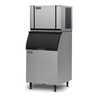
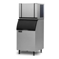
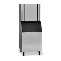
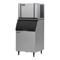
| Type | Commercial Ice Maker |
| Ice Type | Cube |
| Condenser Type | Air-Cooled |
| Daily Ice Production | Varies by model (e.g., 300 lbs to 1000 lbs) |
| Storage Capacity | Varies by model |
| Refrigerant | R404A |
| Electrical | Varies by model (e.g., 208-230V, 1PH, 60Hz) |
| Water Usage | Varies by model |
| Dimensions | Varies by model |
| Voltage | 208-230V |
| Weight | Varies by model |