English
14
SERVICE MODULARI06/2014
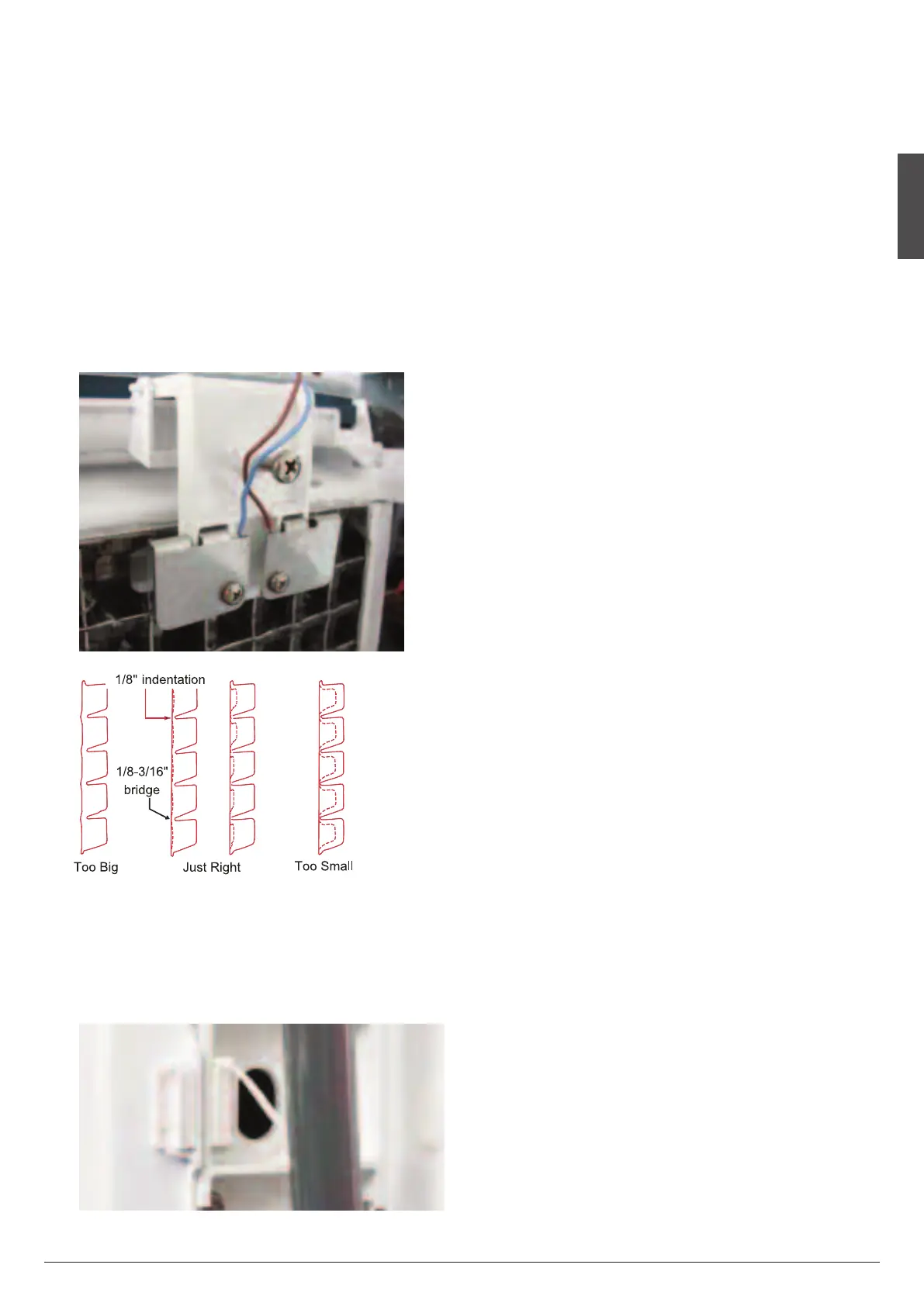
6.4 ICE THICKNESS SENSOR
• Located in the front upper right side off the evaporator, the
s
ensor is made with two metal reeds in which passes power
at low voltage. The two metal reeds, which are individually in
sulated, are set, through a setting screw, to maintain a mini
mum clearence from the evaporator 3÷5 mm.
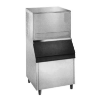
• Once ice is formed into each mold and is thick enough to
fi
llup that minimum clearance existing between the two
sensor reeds and the evaporator, the water that cascades
over the ice has gradually approached to make contact be
tween the two sensor reeds.
• It is enough that this contact remains there for about 10 sec
onds that the P.C. Board receives the signals to put the ice
machine on defrost.
Ice Bridge Thickenss Measurement
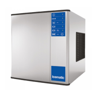
6.5 MAGNETIC SWITCH
• Located in the front of the evaporator plastic curtain, this
switch sends a pulse to the P.C. Board which switches the
machine back in the freezing cycle.
6.6 HOT GAS SOLENOID VALVE
• The Hot Gas Solenoid Valve functions only during the Har
v
est Cycle, to divert the hot discharge gas from the Com
pressor, bypassing the Condendenser and thermostatic
expansion valve, for direct flow to the Evaporator Platen As
sembly to release ice cubes from the ice cube molds.
• The Hot Gas Solenoid Valve is comprised of two parts, the
B
ody & Plunger and the Coil assembles.
Installed in the discharge line of the Compressor, the ener
gized solenoid coil lifts the valve stem within the valve body
to cause the hot discarge gas to be diverted when the ice
Thickness sensor has signalled to the P.C. Board to start the
Harvest Cycle.
6.7 CONDENSER TEMPERATURE SENSOR
• The condenser temperature sensor probe located in con
tact with the condenser tube coil detects the condenser
temperature variations and signals them by supplying cur
rent, at low voltage, to the P.C. BOARD.
In the air cooled versions, in relation to the different current
received, the micro processor of the P.C. BOARD supplies,
through a TRIAC, the power at high voltage to the fan motor
so to cool the condenser and to reduce its temperature.
In case the condenser temperature rises and reaches 65°C
150°F the current arriving to the micro processor is such to
cause an immediate and total stop of the machine operation
with the blinking of the Red LED.
6.8 HIGH PRESSURE CONTROL
• The high Pressure Control, a safety control, is factory set to
cutout, at 30 bar and cutin at 22 bar.
• To shut OFF electrical power to Icemaker, should a loss of
water occur to the water cooled Condenser or a burnt out of
the fan motor on air cooled versions.
• The high Pressure Control is manual reset with reset button
B located on the Front Console Panel.
6.9 WATER REGULATING VALVE
Water Cooled Models
• The Water Regulating Valve functions maintain a constant
Compressor head pressure, by regulating the amount of in
coming water flow through the Condenser, on watercooled
models.
• The valve operate through the refrigerant system high side
pressure. Rotating the adjusting screw located on top of the
valve, can INCREASE or DECREASE the water flow through
the watercooled Condenser, which in turn, will DECREASE
or INREASE the Compressor operating head pressure.