WARNING!
:
T
roubleshooting to be performed by qualied technicians
only. High voltage is dangerous – can cause injuries, death or property damage.
Troubleshooting
Symptom Remedy
Low speed
fan runs
continuously
• Verify you have 24 VAC between the R and C terminals
• Verify the high temperature limit switch is not open
• Check fuse to verify it is not blown
• Verify the fusible link is not damaged
• Temporarily bypass limits for troubleshooting only
No power to
the thermostat
(between R and
C terminals)
• Verify you have 24 volts between the SEC-1 and SEC-2 terminals
• Verify that the high temperature limit switch is not open
• Check fuse to verify it is not blown
• Verify the fusible link is not damaged
• Make sure the door interlock is bypassed while troubleshooting
No fan output in
cool mode
• Verify that you have 24 volts between GC and C
• Check fan connections at HI and COM
• Verify high speed fan operates correctly
No fan output in
heat mode
• Check for 24Vac voltage from R-C
• Check Thermostat call for 24VAC from terminals W to C
• Check Connections of Gas 1 and Gas 3
– Check for 24VAC from the Gas 1 terminal to C and from the Gas 3 terminal to
C on the ICM271. If there is no voltage at either of these points, the fan will not
work. Check for defective gas valve or loose /brokpen wires.
• VDP jumper plug broken off board.
• Check the Gas 1 – Gas 3 Jumper (on furnaces without ame proving circuit only)
– The GAS1-to-GAS3 connection is made by a three-wire ame-proof switch, but in
some standing-pilot applications this device is not present. In such applications, a
jumper must be installed between GAS1 and GAS3 terminals.
– A jumper should only be used on applications where a jumper exists on the
original equipment furnace fan control board when no ame proving switch
is installed. This jumper should also include a male 1/4” spade connector to
connect to your current gas valve’s wiring harness.
• Check fan connections at LO and COM
• Verify low speed fan operates correctly
Fan cycles on
and off
• Transformer may be damaged and creating an irregular sine wave
• Thermostat output signal may be outputting an irregular sine wave (especially solid state
thermostats)
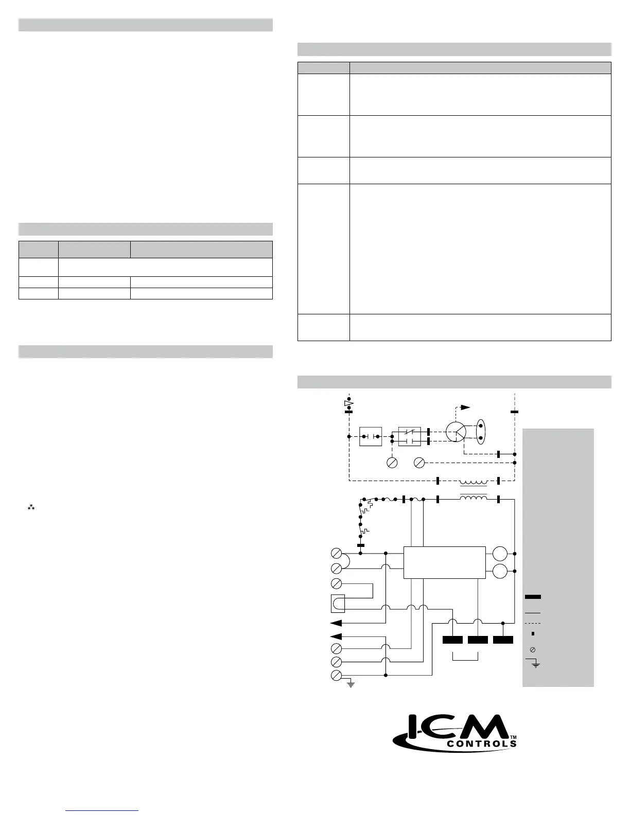
Legend:
AUXLS Auxiliary limit switch,
manual reset (SPST-
NC)
(Down ow furnace
models only)
BLWR Blower motor relay
(SPST-NO)
BVSS Blocked vent shut-off
switch, manual reset
(SPST-NC)
CAP Run capacitor
FL Fusible link
HI/LO Blower motor speed
change relay (DPST)
ITLK Blower door interlock
switch (SPST-NO)
LS Limit switch auto reset
(SPST-NC)
MTR Motor blower
TRANS Transformer
VDP Vent damper jumper
plug
Printed circuit
board terminal
24 VAC wiring
115 VAC wiring
Circuit on printed
circuit board
Screw terminal
Equipment ground
Not on all furnace
models
*
SEC-1
ITLK
HI/LOBLWR
LINE-1
EAC-2EAC-1
115 VAC
TRANS
24 VAC
SEC-2
PR-1 PR-2
COM
LINE-2
MTR
LO
HI
FUSEFLLS
*
BVSS
*
AUXLS
R
GH
W
VDP
GC
Y
C
GAS1 GAS3 GAS2
HI/LO
BLWR
LIM-1
LIM-2
JW-1
*
CAP
MICROPROCESSOR
Jumper
position
(if required)
Wiring Diagram
Installation Instructions
1. Be sure all electrical power is turned off.
2. Remove control box cover, exposing the old Carrier/BDP gas
furnace control center.
3. If furnace is equipped with a vent damper, disconnect the plug
connector from the old board.
4. Tag each wire as it is disconnected from the old furnace control
center. Disconnect all of the wiring hookups.
5. Remove the old Carrier/BDP furnace control center from the
control box.
6. Install the ICM271 fan control center into the control center box. Be
sure the top edge of the ICM271 is in the mounting slot, just like
the original board.
Note: If the ICM271 is not installed correctly (i.e. behind the
slot), an electrical short could occur.
7. Reconnect all of the wires (removed in Step 4, above) to the proper
terminals.
8. If the appliance had a vent damper, break the vent damper jumper
plug from the ICM271. Connect the original vent damper plug onto
the ICM271.
9. Restore electrical power to the furnace and put the furnace into
operation. Allow the furnace to run through one complete heating
or cooling cycle.
10. If the furnace is functioning properly, replace all panels and leave
this instruction sheet with the homeowner.
7313 William Barry Blvd., North Syracuse, NY 13212
(Toll Free) 800-365-5525 (Phone) 315-233-5266 (Fax) 315-233-5276
www.icmcontrols.com
ONE-YEAR LIMITED WARRANTY
The Seller warrants its products against defects in material or workmanship for a period of
one (1) year from the date of manufacture. The liability of the Seller is limited, at its option,
to repair, replace or issue a non-case credit for the purchase prices of the goods which are
provided to be defective. The warranty and remedies set forth herein do not apply to any
goods or parts thereof which have been subjected to misuse including any use or application
in violation of the Seller’s instructions, neglect, tampering, improper storage, incorrect
installation or servicing not performed by the Seller. In order to permit the Seller to properly
administer the warranty, the Buyer shall: 1) Notify the Seller promptly of any claim, submitting
date code information or any other pertinent data as requested by the Seller. 2) Permit the
Seller to inspect and test the product claimed to be defective. Items claimed to be defective
and are determined by Seller to be non-defective are subject to a $30.00 per hour inspection
fee. This warranty constitutes the Seller’s sole liability hereunder and is in lieu of any other
warranty expressed, implied or statutory. Unless otherwise stated in writing, Seller makes no
warranty that the goods depicted or described herein are t for any particular purpose.
LIAF044-2
• Turn off gas supply and electrical power to equipment before
servicing
CAUTION!
:
Do not use this option on paired furnace
applications.
The ICM271 has different blower speed options to match a specic
application (see chart). The blower speed option used on the original
furnace control may be very difcult to determine.
1. If the old Carrier/BDP unit has (2) black relays just like the ICM271,
then look for the JW1 jumper and R17 resistor on the Carrier/BDP
board. They will be in the same location as the JW1 and R17 on
the ICM271. If either one (JW1 or R17) has been cut, then cut the
ICM271 equivalent. This will match the original Carrier/BDP blower
speed option.
Blower Speed Output
Input From
Thermostat
ICM271
As Shipped
G Blower Operation
(Cut R17 Resistor)
W
Lo-Speed Heating Blower with
75 seconds ON Delay and 105 seconds OFF Delay
G Hi-speed cooling blower Lo-speed heating blower
Y No blower Hi-speed cooling blower with 90 second OFF delay
Blower Operating Modes
 Loading...