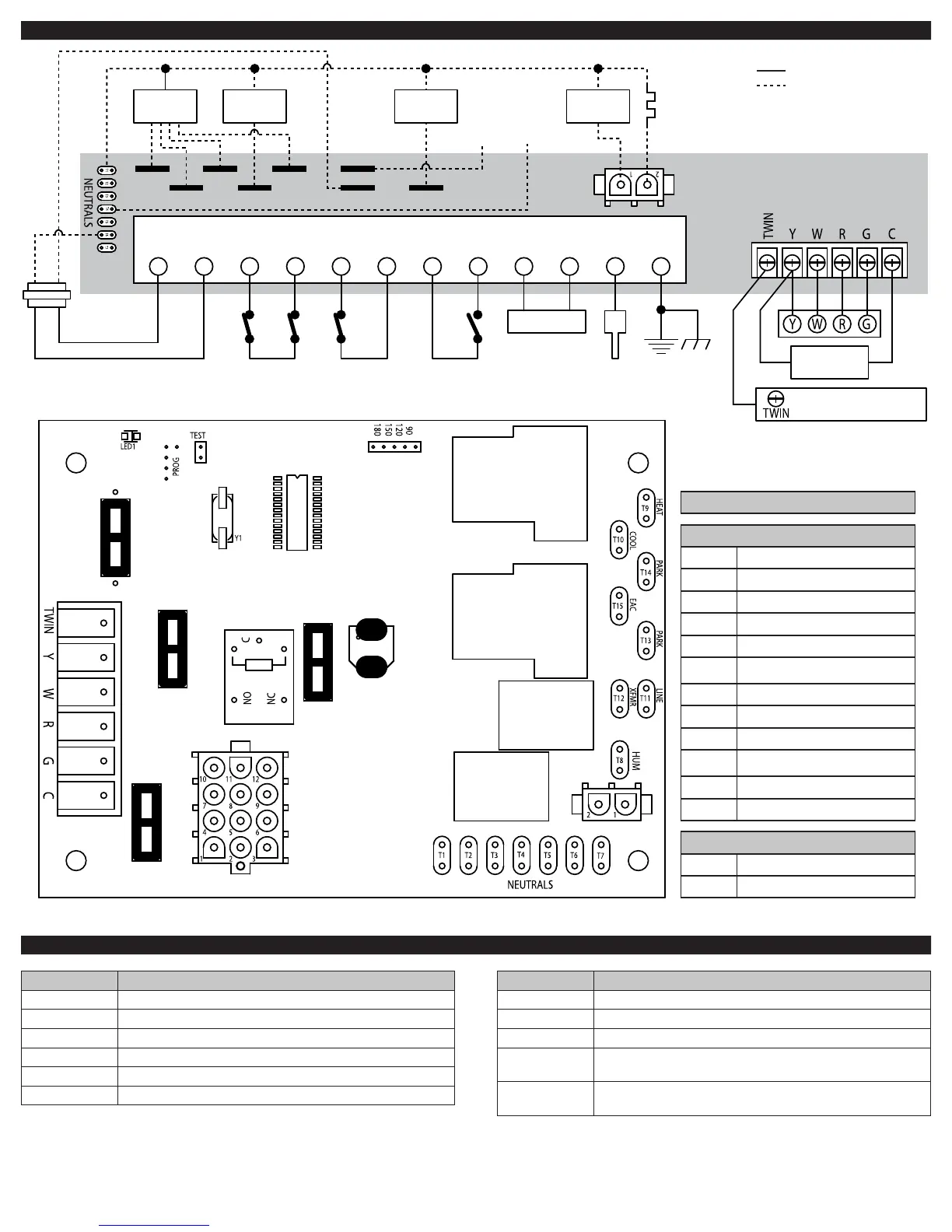
WIRING DIAGRAM
24
VAC
LIM
IN
24
COM
LIM
OUT
RO
IN
RO
OUT
PS
IN
PS
OUT
GV GV FS GND
Gas Valve
COOL
HEAT
EAC
PARK PARK LINE
XFMR HUM
24 VAC 120 VAC
Hot
120 VAC
Neutral
Electronic
Air Cleaner
Circulator
Blower
Ignitor
(120 VAC)
Humidifier
Limit
Switches
(N.C.)
Rollout
Switches
(N.C.)
Pressure
Switches
(N.O.)
Flame
Sensor
Probe
Compressor
Contactor
Twinning with two
ICM2810 controls only
Low voltage (24 VAC)
High voltage (120 VAC)
N.C. = Normally closed switch
N.O. = Normally open switch
Inducer
FAULT CODES
LED FAULT CONDITION
ON No fault
OFF Control failure
1 flash System lockout
2 flashes Pressure switch stuck closed
3 flashes Pressure switch stuck open
4 flashes Open limit switch
LED FAULT CONDITION
5 flashes Flame has been sensed when no flame should be present
6 flashes Open rollout switch
7 flashes Low flame sense signal
8 flashes C terminal must be grounded to frame of furnace or you
have a faulty thermostat
Continuous
Flashing
115 VAC AC power reversed
PIN CONNECTIONS
12-Pin Connections
Pin 1
Limit switch (W) (input)
Pin 2
Flame sense input
Pin 3
24 VAC input
Pin 4
Pressure switch (output)
Pin 5
Rollout switch (XFMR) (input)
Pin 6
Common
Pin 7
Limit switch (output)
Pin 8
Gas valve common
Pin 9
Common
Pin 10
Pressure switch (input)
Pin 11
Rollout switch (output)
Pin 12
Gas valve output
2-Pin Connections
Pin 1
Inducer blower
Pin 2
Hot surface ignitor