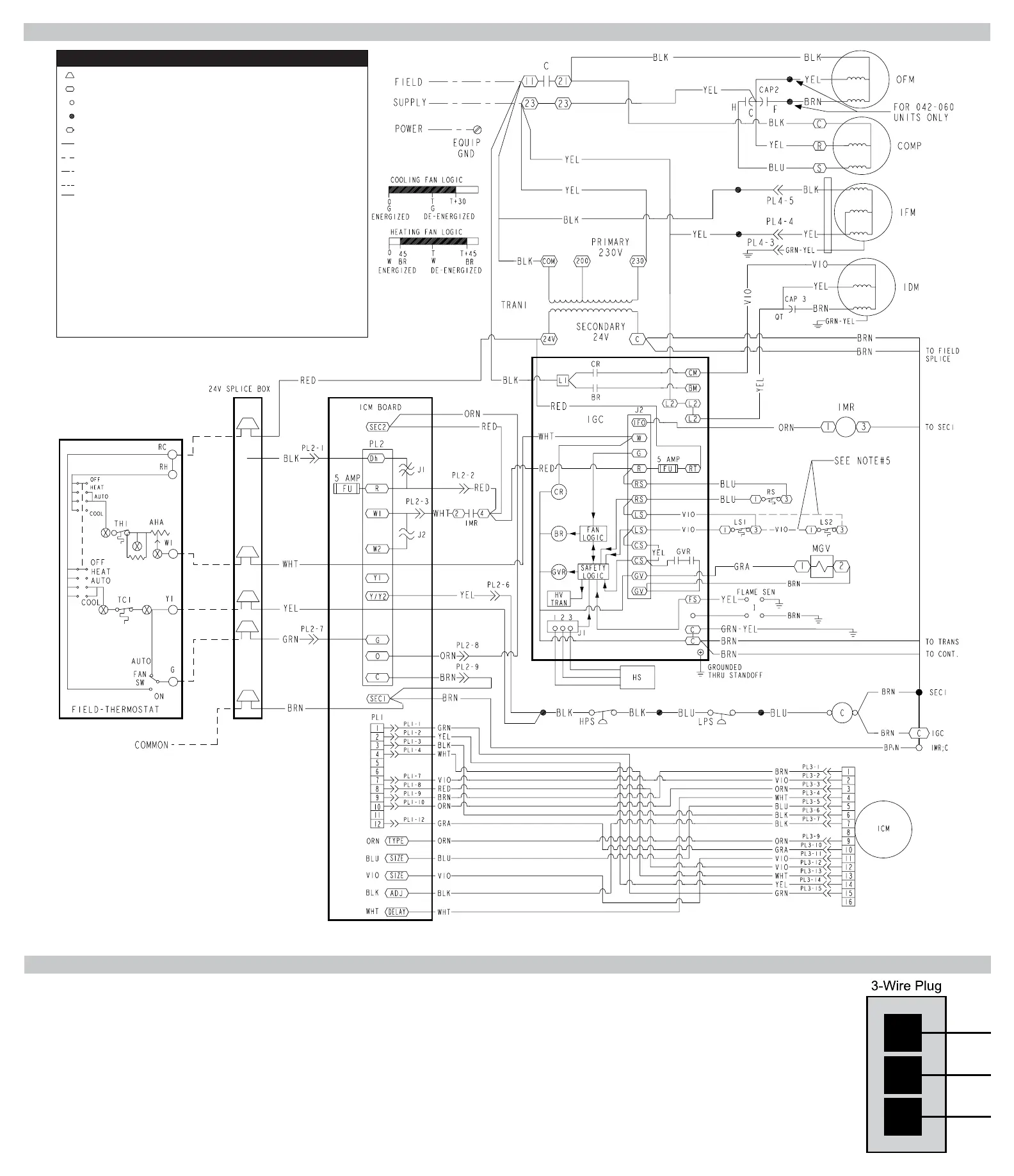
Typical Wiring Diagram
LEGEND
Field Splice
Terminal (marked)
Terminal (unmarked)
Splice
Splice (marked)
Factory Wiring
Field Control Wiring
Field Power Wiring
Accessory or Optional Wiring
To Indicate Common Potential
Only: Not to Represent Wiring
BR Blower Relay
C Contactor
CAP Capacitor
COMP Compressor Motor
CR Combustion Relay
EQUIP Equipment
FS Flame Sensor
FU Fuse
GND Ground
GVR Gas Valve Relay
HPS High Pressure Switch
HS Hall Effect Sensor
HV TRAN High Voltage Transformer
I Ignitor
ICM Integrated Control Motor
IDM Induced Draft Motor
IFM Indoor Fan Motor
IGC Integrated Gas Unit
Controller
IMR Indoor Motor Relay
LPS Low Pressure Switch
LS Limit Switch
MGV Main Gas Valve
OFM Outdoor Fan Motor
QT Quadruple Terminal
RS Rollover Switch
TRAN Transformer
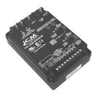
Testing the Inducer Motor
Testing the Inducer Motor Hall Effect switch using a Voltmeter capable of reading DC Voltage
• Withthethreewireplugconnectedandpowerapplied,useaVoltmetersettoDCVandconnectthenegative (-) meter lead to pin 3andthepositive lead (+) to pin 1.Carefully
rotatetheinducerdraftmotorbyhand180degreesandthereadingshouldbeless than 1 Volt DC.Continuetorotatethemotorthrough180degreestowards360degrees.The
voltageshouldincreasetoareadingbetween6.5 VDC and 9VDCatthefull360degreemark.Iftherstreadingislessthan1VDCorthesecondreadingisnotbetween6.5&9
VDC,youshouldreplacethesensor.
• Next,movethepositive lead of the meter to pin 2leavingthenegative lead on pin 3.TakeareadingwithyourDCVmeterandthereadingshouldmeasurebetween16.5VDC
and 21VDC.Replacethesensorifthereadingisnotinrange.
• IfCode6ashesontheboard,checkforcontinuityacrossthejumperatJ2.Thejumpershouldnotbecutandshouldhavefullcontinuity.
1
2
3