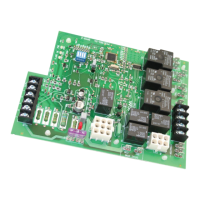
ICM281
Fixed Speed Furnace Control Replacement Module
Replaces: Carrier CESO110057-00, CESO110057-01, CESO110057-02
Safety Considerations
Only trained personnel should install or service heating equipment.
When working with heating equipment, be sure to read and
understand all precautions in the documentation, on labels, and
on tags that accompany the equipment. Failure to follow all safety
guidelines may result in damage to equipment, severe personal
injury or death.
Introduction
The ICM281 xed speed furnace control replaces the following
Carrier/BDP modules: CESO110057, CESO110057-1,
CESO110057-2, CESO110048, CESO110020, and HH84AA016
The ICM281 has incorporated LED diagnostics to assist in
troubleshooting.
It is recommended that a sight glass (not included) be installed
in a convenient location on the furnace to take advantage of this
feature. If a sight glass is not installed, the self-test feature of the
board can still be used for routine troubleshooting. A fault code label
is included in this package and must be installed on the furnace.
Electrostatic Discharge (ESD) Precautions
CAUTION!
Use caution when installing and servicing the furnace to avoid
and control electrostatic discharge; ESD can impact electronic
components. These precautions must be followed to prevent
electrostatic discharge from hand tools and personnel. Following
the precautions will protect the control from ESD by discharging
static electricity buildup to ground.
1. Disconnect all power to the furnace. Do not touch the control
or the wiring prior to discharging your body’s electrostatic
charge to ground.
2. To ground yourself, touch your hand and tools to a clean,
metal (unpainted) furnace surface near the control board.
3. Service the furnace after touching the chassis. Your body
will recharge with static electricity as you shufe your feet or
move around, and you must reground yourself.
4. Reground yourself if you touch ungrounded items.
5. Before handling a new control, reground yourself; this will
protect the control. Store used and new controls in separate
containers before touching ungrounded objects.
6. ESD damage can also be prevented by using an ESD service
kit.
CAUTION!
Failure to turn off gas and electric supplies can result in
explosion, re, death, or personal injury.
6. Disconnect thermostat wires and humidier wires (if equipped
with a humidier).
7. Disconnect line voltage, blower, electronic air cleaner wires (if
equipped), and transformer wires.
8. Remove wiring harness edge connector and gasket from
circuit board.
9. Remove screws or any other fasteners and old circuit board.
10. Examine control and control box to check for water stains.
11. Make repairs if any sources of water leakage are found.
Be sure to check humidiers, evaporator coils, and vent
systems in the area of the control.
Step 2: Install the New Control
1. Ground yourself. When handling circuit board, hold it by the
edges.
2. For 90 percent efcient furnaces, clip JW9 jumper wire. The
JW9 jumper is found close to the right hand corner of the
circuit board, beneath the HUM-1 terminal (see Figure 1).
This will result in a 15-second inducer OFF delay.
3. Insert board’s edge between control box tabs.
4. Fasten circuit board with retaining screws.
IMPORTANT:
For 58EJA or 349MAV horizontal furnaces, the bottom control
board bracket may need to be notched and trimmed to pre-
vent the LED and circuit trace from interfering with the mount-
ing bracket. This may cause a short and result in damage to
the control.
To prevent:
a. Remove the mounting bracket from the control box.
b. Mark, notch and trim the bracket between where the
bottom center and bottom right mounting holes/pins align.
Be sure to trim enough of the bracket so the circuitry on
the underside of the control board lies clear of the bracket.
Step 1: Remove Existing Control
CAUTION!
To service control, and prior to disconnection, label all wires.
Failure to do so may result in wiring errors can cause dangerous
operation.
1. Turn thermostat to OFF position or set it to the lowest
possible setting.
2. Turn OFF electrical supply to furnace.
3. Turn OFF gas supply to furnace.
4. Remove furnace blower and control access doors.
5. Remove control box cover.
• Controls gas valve, ignitor, blower motor, inducer, humidifier and air cleaner
• Microprocessor-based
• Designed for 100% gas shutoff in case of ignition failure
• Twinning compatible with other ICM281 boards
• Reverse polarity protection
• Secondary brownout voltage protection
• Compatible with 24 VAC standard thermostat
• Provides diagnosti
c LED to aid in troubleshooting
Specifications
Electrical
• Voltage Range: Line (98 to 132 VAC) @ 60Hz
• Ignitor: 5A @ 120 VAC
• Cool Blower: 30A, 2HP, 240 VAC
• Heat: 5A, 1/2 HP, 240 VAC
• Inducer Motor: 4A, FLA-8.0 LRA @ 120 VAC
• Gas Valve: 1.5A @ 30 VAC
Features