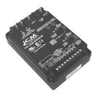
ICM333
Head Pressure Control with
Optional Heat Pump Override
Regulates head pressure via
temperature or pressure input
Installation, Operation & Application Guide
For more information on our complete range of American-made
products – plus wiring diagrams, troubleshooting tips and more,
visit us at www.icmcontrols.com
Caution!
Installation of the ICM333 shall be performed by trained technicians only. Adhere to all local and national electric codes. Disconnect all power to the system before making any connections.
• Line voltage:120,208,240,277,480and600VAC
• Control voltage:18-30VAC
• Frequency:50-60Hz
• Operating temperature:-40ºFto+176ºF(-40°Cto+75°C)
• Probes: –Temperature:Thermistor,10Kohmat77°F(25°C)
–Pressure:ICM380(orderedseparately)
• Heat pump override:24VACN.C.orN.O.
• Weight:12ounces(341grams)
Specifications
Note: TheICM333shouldbeappliedtomotorsandequipmentthathavebeendesignatedbytheir
respectivemanufacturersascapableofbeingspeedcontrolled.
• Mounting:
– Surfacemountusing(2)#8screws
– TheICM333shouldbesurfacemountedtoacleanmetalorotherthermallyconductivesurface
formaximumheatdissipation
– ItisrecommendedthattheICM333bemountedawayfromthecondenserexhaustairinorderto
maintainloweroperatingtemperatures
LIAF010-1
7313 William Barry Blvd., North Syracuse, NY 13212
(Toll Free) 800-365-5525 (Phone) 315-233-5266 (Fax) 315-233-5276
www.icmcontrols.com
ONE-YEAR LIMITED WARRANTY
TheSellerwarrantsitsproductsagainstdefectsinmaterialorworkmanshipforaperiodofone(1)
yearfromthedateofmanufacture.TheliabilityoftheSellerislimited,atitsoption,torepair,replace
orissueanon-casecreditforthepurchasepricesofthegoodswhichareprovidedtobedefective.
Thewarrantyandremediessetforthhereindonotapplytoanygoodsorpartsthereofwhichhave
beensubjectedtomisuseincludinganyuseorapplicationinviolationoftheSeller’sinstructions,
neglect,tampering,improperstorage,incorrectinstallationorservicingnotperformedbytheSeller.
InordertopermittheSellertoproperlyadministerthewarranty,theBuyershall:1)NotifytheSeller
promptlyofanyclaim,submittingdatecodeinformationoranyotherpertinentdataasrequestedby
theSeller.2)PermittheSellertoinspectandtesttheproductclaimedtobedefective.Itemsclaimed
tobedefectiveandaredeterminedbySellertobenon-defectivearesubjecttoa$30.00perhour
inspectionfee.ThiswarrantyconstitutestheSeller’ssoleliabilityhereunderandisinlieuofanyother
warrantyexpressed,impliedorstatutory.Unlessotherwisestatedinwriting,Sellermakesnowarranty
thatthegoodsdepictedordescribedhereinaretforanyparticularpurpose.
Example
1.Onlyoneprobetypecanbeusedatatime,temperatureorpressure.Uptotwo
probesofakindcanbeusedinwhichcasethecontrolwillrespondtotheprobe
thatsensesthehighesttemperatureorpressure.
2.AtypicalinstallationisshowninAppendix.Thetemperatureprobecanbe
attachedtotheU-bend.Usetheprovidedthermo-tapetosecuretheprobetothe
placeofattachment.
3.Whenusingapressureprobe,installitonthedischargelinetransducertting.
4.TemperatureandPressureprobesareconnectedtoICM333asshownin
respectivewiringdiagramsbelow.
Installing and Connecting the Probe
BLUE
WHITE
GREEN
RED
BLACK
PRESSURE TRANSDUCER
2
BLUE
WHITE
GREEN
RED
BLACK
PRESSURE TRANSDUCER
1
TEMPERATURE
PROBE
1
TEMPERATURE
PROBE
2
Connections for ICM333 at 120/208/240/277 VAC
1.Removepowerfromsystem.
2.FieldinstallawirefromLine 1wiretoLine 1terminal.
3.CutLine 2wire;afxmotorsidetoMotor 2terminal
andlinesidetoLine 2terminal.
4.Make24VACandtemperatureprobeconnections.
5.Verifywiringiscorrect.
6.Powerupsystemandcheckoperation.
Typical
condenser fan
PSC
Fan
Motor
Run
Capacitor
120/208/240/277
VAC
PSC
Fan
Motor
Run
Capacitor
Field
Installed
Wire
Line
1
120/277
VAC
Line
2
Motor
2
120/208/240/277
VAC
Connections for Heat Pump System at 120/208/240/277 VAC
1.Removepowerfromsystem.
2.FieldinstallawirefromLine 1wiretoLine 1terminal.
3.CutLine 2wire;afxthecommonfromthedefrost
board’sfanrelaytotheMotor 2terminalandtheLine
fromthecontactortotheLine 2terminal.
4.Make24VAC,probeandHPconnections.
5.Verifywiringiscorrect.
6.Powerupsystemandcheckoperation.
Field
Installed
Wire
PSC
Fan
Motor
Run
Capacitor
Fan
Relay
COM NC
Defrost Board
120/208/240/277
VAC
Line
1
120/240/277
VAC
Line
2
Motor
2
Connections for Heat Pump System at 480/600 VAC
1.Removepowerfromsystem.
2.FieldinstallawirefromLine 1wiretoLine 1terminal.
3.CutLine 2wire;afxthecommonfromthedefrost
board’sfanrelaytotheMotor 2terminalandtheLine
fromthecontactortotheLine 2terminal.
4.Make24VAC,probeandHPconnections.
5.Verifywiringiscorrect.
6.Powerupsystemandcheckoperation.
Connections for ICM333 at 480/600 VAC
1.Removepowerfromsystem.
2.FieldinstallawirefromLine 1wiretoLine 1terminal.
3.CutLine 2wire;afxmotorsidetoMotor 2terminal
andlinesidetoLine 2terminal.
4.Make24VACandtemperatureprobeconnections.
5.Verifywiringiscorrect.
6.Powerupsystemandcheckoperation.
Typical
condenser fan
PSC
Fan
Motor
Run
Capacitor
Line
1
Line
2
Motor
2
Field
Installed
Wire
PSC
Fan
Motor
Run
Capacitor
Line
1
Line
2
Motor
2
Field
Installed
Wire
PSC
Fan
Motor
Run
Capacitor
Fan
Relay
COM NC
Defrost Board