DuringtheHard Startmode,fullvoltageisappliedtothemotorduringstartuptoovercomewindmillingandtolubricatethebearings.
Thepositionofthehardstartdialdeterminesthetimeperiodofthehardstartmode.Thedialcanbeadjustedbetween0.2secondsandapproximately4seconds.
Setthehardstartdialaccordingtothetypeofmotoryouhave.Ifyouhaveaball bearing motor,setthehardstartdialtotheMINposition.Ifyouhaveasleeve bearing motor,setthe
hardstartdialtothemiddleofthesleevebearingrange.
Afteryoubeginattherecommendedsetting,youcannetunethehardstarttimewithintherecommendedrangeforthetypeofmotoryouhave.
Itisrecommendedthatyouusetheminimumpossiblehardstarttimetoavoidblowingtoomuchcoldairoverthecondenser.
Thehardstartmodeappliesfullvoltagetothemotorforthesettimeperiod.Afterwards,themotorspeedisdictatedbythetemperaturesensor(s).
Setting the Hard Start Speed
Thecutoutspeeddialadjuststhemotorvoltagerange.Setthecutoutvoltagedialaccordingtothetypeofmotoryouhave.
Sleeve Bearing Motors: Setthecutoutspeeddialtothemiddleofthesleevebearingrange.Inthisrange,themotorcanrundownapproximately40-50%of
thefulllinevoltage,whichallowssufcientRPMsforcoolingandlubrication.
CAUTION!:
Withsleevebearingmotors,itisimportantnottoadjustoutsidethesleevebearingrangeorbearingfailuremayresult.
Ball Bearing Motors:SetthecutoutspeeddialtotheMINpositionintheballbearingrange.Thispositionoffersthegreatestrangeofspeedcontrol.Atthe
MINsettingthemotorcanrundowntoapproximately20-30%ofthefulllinevoltage.
Note:Afterstartingattherecommendedsettingsforeithersleeveorballbearingmotors,youcannetunethecutoutspeedtoachievethedesiredresults.
Setting the Cutout Speed
Mode of Operations
Whenusingtemperatureprobes,thecontrolwillmaintaincondensertemperaturebetween7°Faboveand7°FbelowdialedTemperatureSetpoint.ThedialTemperatureSetpointrangeis70°Fto140°F
Whenusingpressureprobes,thecontrolwillmaintaincondenserpressurebetween20psigaboveand20psigbelowdialedPressureSetpoint.ThedialPressureSetpointrangeis35psigto465psig.
Theisnocorrelationbetweendialtemperatureandpressurescalesonthecontrol
Whenthemotorstartsrunningitwillhardstartforthelengthoftimedictatedbythehardstartdialsetting.Afterthehardstarttimehaselapsed,themotorspeediscontrolledbytheprobereading,temperatureor
pressure.Thegreenlightturnsonwhenthemotorrunsatfullspeed.
Asthesensedtemperature/pressuredecreases,theoutputvoltagedecreases.Theyellowlightturnsonduringmotorvariablespeed.Theoutputvoltagemaydecreasetothedeterminedcutoutspeeddictatedby
thecutoutspeeddial.Uponreachingthecutoutspeedsetting,theoutputvoltagegoestozerovolts.Theyellowlightturnsoff.
Appendix BAppendix A
°C °F Resistance (KΩ)
0° 32° 32.7
5° 41° 25.4
10° 50° 19.9
15° 59° 15.7
20° 68° 12.5
25° 77° 10.0
30° 86° 8.1
35° 95° 6.5
40° 104° 5.3
45° 113° 4.4
50° 122° 3.6
Pressure
(psig)
Voltage
(Vdc)
0 0.5
50 0.9
100 1.3
150 1.7
200 2.1
250 2.5
300 2.9
350 3.3
400 3.7
450 4.1
500 4.5
Temperature vs. Probe Resistance Pressure vs. Voltage
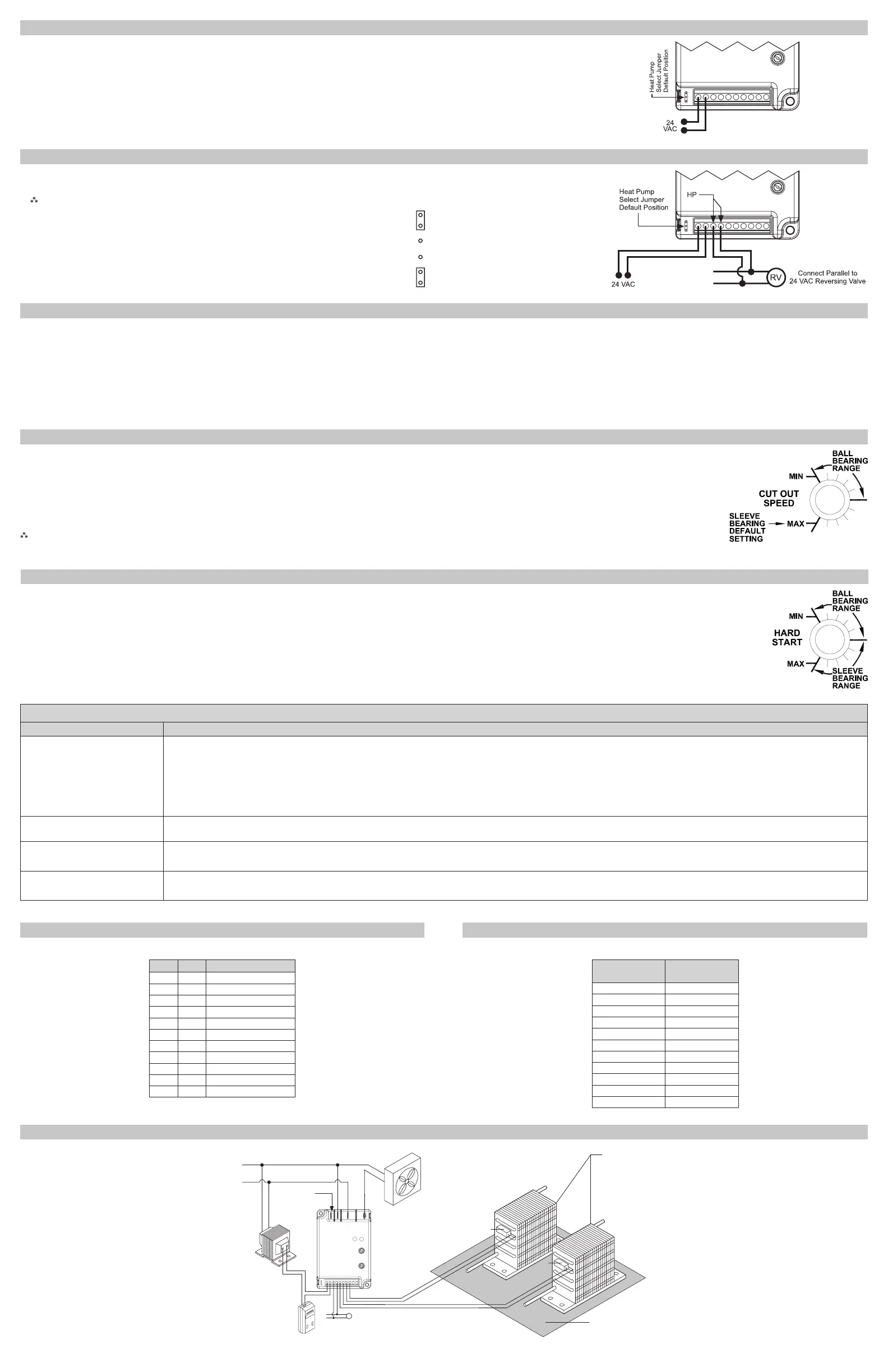
1.TheHeat Pumpterminalsacceptthe24VACsignalfromthereversingvalveholdingcoil.Makeaparallel
connectionfromthereversingvalvetotheHPterminals.
Note:Do not apply a voltage higher than 30 VAC to the HP terminals.
2.IftheHeat PumpisintheHeatingmodeandthereversingvalveisenergized,then
theHeat Pump SelectjumpermustbeintheDefault(N.O.)position.
3.IftheHeat PumpisintheHeatingmodeandthereversingvalveisnotenergized,
thentheHeat Pump SelectjumpermustbeintheN.C.position.
N.O.
N.C.
Connections for Heat Pump Systems
Troubleshooting
Symptom Problem
Unitfailstostart UsinganACvoltmeter,measurethevoltagebetweenthe24VACterminals.Itshouldreadapproximately24volts.MeasurethelinevoltagebetweenLINE1andLINE2to
conrmthatlinevoltageispresent.
Iflightsareashingalternativelythennoprobeisconnectedormalfunctionprobe.
Whenusingatemperatureprobe,disconnectitanduseanohmmetertomeasuretheresistancebetweenthewires.ItshouldmatchthechartinAppendixA.
Whenusingapressureprobe,withpowerappliedtothecontroluseavoltmetertomeasurevoltsDCbetweenCOMMandP1orP2,wherethewireisconnected.Thereading
shouldbeaccordingtothechartinAppendixB.
Thefuseisblownand/orsignsof
damageontheunit
Theunithasbeenmiswiredandmaybepermanentlydamaged.
ThefancyclesfromONtoOFF
withlittleornospeedmodulation
Reducehard startstettingtominimumneededtoacceleratethefan.Excessivehardstartcauseslargepressuredropsbyrunningtoomuchcoldairoverthecondenser.
Shouldthecyclingpersist,relocatethetemperatureprobeupthecondensertoincreasesensitivitytotemperaturechangeand/oradjustthetemperaturesetpoint.
Thehighpressureswitchtripsoff SeeUnitfailstostartabove
Checkthesetpointandreduceitifneeded
1.For non-heat pump applications,theheatpumpselectjumpermustbeintheDefault(N.O.)position,andtheHPterminalsmustbeleftunconnected.
2.SettheCutoutSpeedandtheHardStartTimetotheappropriatepositionsforthetypeofmotoryouhave(seebelow).
Connections for Air Conditioning Only
ICM333 Typical Installation
Condenser
Sensor
Sensor
Sensor
ICM333
canmonitor
twocondensers
Motor
1
Motor
2
ReversingValvefor
HeatPump
T-Stat
Control
Transformer
Line2
LineVoltage
Terminalto
beusedfor
480/600VAC
Line1

 Loading...