EasyManua.ls Logo

ICM Controls ICM292 - User Manual

ICM Controls ICM292
2 pages
Print Icon
To Next Page IconTo Next Page
Loading...
7313 William Barry Blvd.
North Syracuse, NY 13212
ICM CONTROLS 800.365.5525
www.icmcontrols.com
LIAF107-1
FEATURES SPECIFICATIONS
ICM292
Gas Ignition Control Board
• Control voltage:24VAC(18-30VAC),60Hz
• Line voltage:115VAC,60Hz
• Power consumption:0.3Aplusgasvalvecurrentat24VAC
• Operating temperature:-40°C(-40°F)to75°C(176°F)
Timing
• Pre-purge:30seconds
• Trial for ignition:7seconds
• Retries:Twogroupsoftwo,30secondsdelaywithinthe
groupand3minutesdelaybetweengroups
• Lockout:1hour
• Post-purge:90,120,160and180seconds
Inputs
• Power:24VACandCOM
• Thermostat interface:R,W,YandG
• System switches:VentPressureandLimitswitches
(MainandOver-temperatureswitchesinseries)
• Flame Sensing
• Heat blower OFF delay: SW1toggleswitch
Install New Control
1. Groundyourself.Whenhandlingcircuitboard,holditbytheedges.
2. Fastencircuitboardwithretainingscrews.
3. Connectalllinevoltage,lowvoltage,andaccessorywires.
4. Verifythesequenceofoperation.
Safety Considerations
Onlytrainedpersonnelshouldinstallorserviceheatingequipment.Whenworkingwithheatingequip-
ment,besuretoreadandunderstandallprecautionsinthedocumentation,onlabels,andontags
thataccompanytheequipment.Failuretofollowallsafetyguidelinesmayresultindamagetoequip-
ment,severepersonalinjuryordeath.
Introduction
TheICM292DSIgasignitioncontrolreplacesthefollowingRheemmodel:62-24140-04.TheICM292
hasincorporatedLEDdiagnosticstoassistintroubleshooting.Faultcodeinformationcanbefound
inthisapplicationguide.Pleasekeepthisapplicationguidewiththefurnaceinstallationmanualfor
futurereference.
Electrostatic Discharge (ESD) Precautions
CAUTION!
Use caution when installing and servicing the furnace to avoid and control electrostatic discharge;
ESD can impact electronic components. These precautions must be followed to prevent
electrostatic discharge from hand tools and personnel. Following the precautions will protect the
control from ESD by discharging static electricity buildup to ground.
1. Disconnectallpowertothefurnace.Donottouchthecontrolorthewiringpriortodischargingyour
body’selectrostaticchargetoground.
2. Togroundyourself,touchyourhandandtoolstoaclean,metal(unpainted)furnacesurfacenear
thecontrolboard.
3. Servicethefurnaceaftertouchingthechassis.Yourbodywillrechargewithstaticelectricityasyou
shufeyourfeetormovearound,andyoumustregroundyourself.
4. Regroundyourselfifyoutouchungroundeditems.
5. Beforehandlinganewcontrol,regroundyourself;thiswillprotectthecontrol.Storeusedandnew
controlsinseparatecontainersbeforetouchingungroundedobjects.
6. ESDdamagecanalsobepreventedbyusinganESDservicekit.
AWcallfromthethermostatwillengagetheInducerDraftmotor.TheVentPressureswitchcloses.
Ignitionsequencebegins,gasvalveandsparkareengaged,providingthatsystemsafetyswitches
(MainandOver-temperatureswitchesinseries)areclosed.TheBlowermotorwillengageatHEAT
speed20secondsafterameisestablishedandsensed.OnWcallsatisfaction,theInducermotor
turnsoffafter10secondsandBlowermotorturnsoffaccordingtoHeatBlowerOffdelaysetting.
AGcallfromthethermostatwillengageBlowermotorwithoutdelayatFANspeed.Itdisengages
withoutdelaywhenGcallisremoved.
AYcallfromthethermostatwillengageBlowermotorwithoutdelayatCOOLspeed.Itdisengages
45secondsafterYcallissatised.
Sequence of Operation
Flame not established
1. Ifameisnotestablishedduringthe7secondinitialsequencethenthecontrolwillstartthenext
trialforignitionin30seconds.
2. Therewillbetwomoreattemptstoigniteafter3minutedelay,30secondsapartbeforethe
respectivefaultcodeistriggeredandignitiontrialsarestopped.
3.Thegasvalveisenergizedonlyduringtheignitionsequenceof7seconds.
4. Blowermotorisoffuntil20secondsafterameisestablished.
Flame out
1. Flameoutisconsideredwhenameislostduringheating.
2. WhenWsignalispresentandameisnotsensed,thengasvalvewilldisengageuntilthenexttrial
forignition
3. Ifameisnotestablishedontheimmediatesequence(2above)thenthecontrolwillcontinuewith
additionaltrialsforignition
4. InducerandBlowermotorswillcontinuerunningduringameoutscenario
Flame out of sequence
1. FlameoutofsequencerepresentsascenariowhenameissensedwhileWsignalisnotpresent.
2. InducerandBlowermotorswillbeengaged(ifnotalreadyrunning)andkeeprunningforaslongas
thefaultconditionispresent.
3.Thereis1hourlockoutbeforeaWcallcanbeexecutedoronpowerreset
Troubleshooting Tips
LED Fault Codes
Outputs
• Spark:SE
• Gas Valve:GV
• Inducer draft motor:IDM
• Blower motor:FAN,COOLand
HEATspeeds
• Electric Air Cleaner:EAC
• Humidier relay:HUM
• Heat/Cool relay:H/C
LED indicators
• Power, green LED:PWR
• Status, green LED:OK
• Flame status, yellow LED:FLAME

Direct Spark Ignition (DSI) control board
Microprocessor-based
Controls inducer motors, air cleaner (if equipped), humidier (if
equipped), spark ignitor and the gas valve
Monitors timing, trial for ignition, system switches, ame sensing
and lockout
100% lockout safety feature
Compatible with LP or Natural Gas
LED indication for status and fault codes to aid in troubleshooting
Replaces: Rheem 62-24140-04
LEDS Flashes Fault condition
GREEN ON Normaloperation
1Flash Ignitionfailure(4trials)
2Flashes Pressureswitchstuckopen
3Flashes Limitswitchesopen
4Flashes Pressureswitchstuckclosed
5Flashes Twinfault
6Flashes Brownoutvoltage
7Flashes Hotandneutralreversedornoground
Continuous Gasvalverelayshort
YELLOW RapidBlink Flameoutofsequence
SlowBlink Lowameornoame
ON Flamepresent
CAUTION!
To service control, and prior to disconnection, label all wires. Failure to do so may result in wiring
errors that can cause dangerous operation.
Remove Existing Control
1. TurnthermostattoOFFpositionorsetittothelowestpossiblesetting.
2. TurnOFFelectricalsupplytofurnace.
3. TurnOFFgassupplytofurnace.
CAUTION:Failure to turn off gas and electric supplies can result in explosion, re, death, or
personal injury.
4. Removefurnaceblowerandcontrolaccessdoors.
5. Disconnectthermostatwiresandhumidierwires(ifequippedwithahumidier).
6. Disconnectlinevoltage,blower,electronicaircleanerwires(ifequipped),andtransformerwires.
7. Removescrewsandanyotherfasteners,andtheoldcircuitboard.
8. Examinecontrolandcontrolboxtocheckforwaterstains.
9. Makerepairsifanysourcesofwaterleakagearefound.Besuretocheckhumidiers,evaporator
coils,andventsystemsintheareaofthecontrol.
Question and Answer IconNeed help?

Do you have a question about the ICM Controls ICM292 and is the answer not in the manual?

Summary

Safety Guidelines

Installation and Servicing Precautions

Electrostatic Discharge (ESD) Precautions

Steps to prevent electrostatic discharge damage to control board components during installation.

Removing Existing Control

Instructions for safely disconnecting and removing the old control board before replacement.

Installing New Control

Guidelines for properly grounding and connecting the new control board during installation.

Troubleshooting and Diagnostics

Troubleshooting Flame Issues

Guidance for diagnosing flame not established, flame out, and flame out of sequence faults.

LED Fault Code Interpretation

Understanding LED indicator patterns for diagnostic fault codes on the control board.

Wiring and Component Identification

Component Legend and Wire Colors

Explanation of component abbreviations and standard wire color codes used in diagrams.

Wiring Information Notes

Important considerations and notes for wiring installation and motor speed connections.

Electrical Wiring Diagram

Detailed schematic illustrating the connections for the ICM292 ignition control board.

Overview

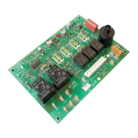
The ICM292 is a Direct Spark Ignition (DSI) control board, designed to manage the operation of gas-fired heating equipment. This microprocessor-based device plays a central role in ensuring the safe and efficient functioning of a furnace by controlling various components and monitoring critical parameters.

Function Description

The primary function of the ICM292 is to orchestrate the ignition sequence and subsequent operation of a gas furnace. It controls the inducer motors, which are responsible for drawing combustion air into the furnace and expelling exhaust gases. The board also manages the operation of an air cleaner and humidifier, if these accessories are installed in the system. Crucially, it controls the spark ignitor, which generates the spark necessary to ignite the gas, and the gas valve, which regulates the flow of gas to the burner.

Beyond simple control, the ICM292 actively monitors several key aspects of the furnace's operation. It tracks the timing of various stages, such as pre-purge (the period before ignition to clear residual gases) and the trial for ignition (the duration during which the ignitor attempts to light the gas). The board also monitors system switches, including vent pressure switches and limit switches, which are vital safety components. Flame sensing is another critical function, where the board detects the presence or absence of a flame after ignition. This continuous monitoring allows the ICM292 to ensure safe operation and respond to any anomalies.

A core safety feature of the ICM292 is its 100% lockout safety mechanism. If the board detects a fault condition that prevents safe operation, it will enter a lockout state, preventing further attempts at ignition until the fault is addressed. This prevents potentially dangerous situations such as unignited gas accumulation. The board is versatile, compatible with both LP (liquid propane) and Natural Gas systems, making it suitable for a wide range of installations.

Usage Features

The ICM292 is designed with ease of troubleshooting in mind, featuring LED indicators that display the current status and fault codes. These LEDs provide valuable diagnostic information, allowing technicians to quickly identify the cause of a problem without needing specialized equipment. For instance, a green LED indicates power and normal operation, while a yellow LED provides information about flame status. Specific flash patterns of the green LED correspond to different fault conditions, such as ignition failure, pressure switch issues, or limit switch problems. This diagnostic capability significantly reduces the time and effort required for servicing.

The board's operation follows a defined sequence. When a call for heat (W signal) is received from the thermostat, the inducer draft motor engages. Once the vent pressure switch closes, indicating proper airflow, the ignition sequence begins, energizing the gas valve and spark ignitor. The blower motor engages at a heat speed after a flame is established and sensed. Upon satisfaction of the W call, the inducer motor turns off, followed by the blower motor according to the set heat blower off delay. The board also manages calls for fan-only operation (G signal) and cooling (Y signal), engaging the blower motor at appropriate speeds and disengaging it when the call is satisfied.

The ICM292 is a direct replacement for Rheem model 62-24140-04, simplifying the upgrade or repair process for existing systems. The inclusion of a wiring diagram in the manual further aids in correct installation and understanding of the connections. The diagram clearly labels various components and their connections, distinguishing between line voltage and low voltage wiring, and indicating factory standard, factory option, and field-installed components.

Maintenance Features

While the ICM292 itself is a control board and not a component that typically undergoes routine maintenance, its design facilitates maintenance and troubleshooting of the overall furnace system. The LED diagnostic codes are a primary maintenance feature, enabling technicians to quickly pinpoint issues within the furnace. For example, if the green LED flashes once, it indicates an ignition failure after four trials, guiding the technician to inspect the ignitor, gas valve, or flame sensor. Other codes point to pressure switch issues, limit switch problems, or even electrical issues like brownout voltage or reversed hot and neutral wires.

The manual provides detailed troubleshooting tips for common scenarios like "flame not established" and "flame out." If the flame is not established during the initial trial, the control will attempt further ignition trials with specific delays, and the gas valve will only be energized during these short ignition sequences. If a flame is lost during heating ("flame out"), the gas valve will disengage, and the control will attempt additional ignition trials. These details help technicians understand the board's logic and diagnose problems more effectively.

For installation and removal, the manual emphasizes critical safety precautions, particularly regarding electrostatic discharge (ESD). Technicians are instructed to ground themselves and their tools before handling the control board to prevent damage to electronic components. This proactive measure ensures the longevity and reliability of the replacement board. The process for removing the existing control involves disconnecting power and gas supplies, labeling wires, and carefully detaching the old board, all steps designed to prevent wiring errors and ensure safety during servicing. When installing a new control, technicians are guided to ground themselves, fasten the board securely, connect all wiring correctly, and verify the sequence of operation, ensuring a proper and safe installation.

ICM Controls ICM292 Specifications

General IconGeneral
Voltage24 VAC
Enclosure MaterialPlastic
Termination TypeScrew Terminal
Flame Current Input0.5μA to 10μA DC
Ignition TypeIntermittent

Related product manuals