7313 William Barry Blvd.
North Syracuse, NY 13212
ICM CONTROLS 800.365.5525
www.icmcontrols.com
LIAF098-1
Install New Control
1. Groundyourself.Whenhandlingcircuitboard,holditbytheedges.
2. Fastencircuitboardwithretainingscrews.
3. Connectalllinevoltage,lowvoltage,andaccessorywires.
4. Verifythesequenceofoperation.
Safety Considerations
Onlytrainedpersonnelshouldinstallorserviceheatingequipment.Whenworkingwithheating
equipment,besuretoreadandunderstandallprecautionsinthedocumentation,onlabels,andon
tagsthataccompanytheequipment.Failuretofollowallsafetyguidelinesmayresultindamageto
equipment,severepersonalinjuryordeath.
Introduction
TheICM291DSIgasignitioncontrolreplacesthefollowingCarriermodel:LH33WP003A.The
ICM291hasincorporatedLEDdiagnosticstoassistintroubleshooting.Faultcodeinformationcanbe
foundinthisapplicationguide.Pleasekeepthisapplicationguidewiththefurnaceinstallationmanual
forfuturereference.
Electrostatic Discharge (ESD) Precautions
CAUTION!
Use caution when installing and servicing the furnace to avoid and control electrostatic discharge;
ESD can impact electronic components. These precautions must be followed to prevent
electrostatic discharge from hand tools and personnel. Following the precautions will protect the
control from ESD by discharging static electricity buildup to ground.
1. Disconnectallpowertothefurnace.Donottouchthecontrolorthewiringpriortodischargingyour
body’selectrostaticchargetoground.
2. Togroundyourself,touchyourhandandtoolstoaclean,metal(unpainted)furnacesurfacenear
thecontrolboard.
3. Servicethefurnaceaftertouchingthechassis.Yourbodywillrechargewithstaticelectricityasyou
shufeyourfeetormovearound,andyoumustregroundyourself.
4. Regroundyourselfifyoutouchungroundeditems.
5. Beforehandlinganewcontrol,regroundyourself;thiswillprotectthecontrol.Storeusedandnew
controlsinseparatecontainersbeforetouchingungroundedobjects.
6. ESDdamagecanalsobepreventedbyusinganESDservicekit.
CAUTION!
To service control, and prior to disconnection, label all wires. Failure to do so may result in wiring
errors that can cause dangerous operation.
1. TurnthermostattoOFFpositionorsetittothelowestpossiblesetting.
2. TurnOFFelectricalsupplytofurnace.
3. TurnOFFgassupplytofurnace.
CAUTION:Failuretoturnoffgasandelectricsuppliescanresultinexplosion,re,death,or
personalinjury.
4. Removefurnaceblowerandcontrolaccessdoors.
5. Disconnectthermostatwiresandhumidierwires(ifequippedwithahumidier).
6. Disconnectlinevoltage,blower,electronicaircleanerwires(ifequipped),andtransformerwires.
7. Removescrewsandanyotherfasteners,andtheoldcircuitboard.
8. Examinecontrolandcontrolboxtocheckforwaterstains.
9. Makerepairsifanysourcesofwaterleakagearefound.Besuretocheckhumidiers,evaporator
coils,andventsystemsintheareaofthecontrol.
Remove Existing Control
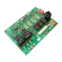
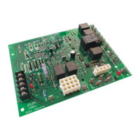
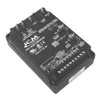
ICM291
Gas Ignition Control Board
AWcallfromtheT’statwillengagethecombustionmotor.Ignitionsequencebegins,gasvalveand
sparkareengaged,providingthatsystemsafetyswitches(RS,LS,andCS)areclosedandthereis
feedbackfromthecombustionmotorHallEffectsensor.Theblowerandindoormotorswillengage45
secondsafterameisestablishedandsensed.Theydisengage45secondsafterWcallissatised.
AGcallfromtheT’statwillengageblowerandindoormotorsrightaway.Theydisengage25seconds
afterGcallisremoved.
Sequence of Operation
Flame not established
1. Ifameisnotestablishedduringthe5+2initialsequencethenthecontrolwillstartthenexttrialfor
ignitionin20seconds.
2. Theattempttoignitewillcontinuefor15minutesbeforetherespectivefaultcodeistriggeredand
ignitiontrialsarestopped.
3.Thegasvalveisenergizedonlyduringtheignitionsequenceof5+2seconds.
4. Blowerandindoorfanmotorsareoffuntilameisestablishedand45secondslater.
Flame out
1. Flameoutisconsideredwhenameislostduringheating.
2. WhenWsignalispresentandameissensedoutthenthesparkwillstartrightaway.
3. Ifameisnotestablishedontheimmediatesequence(2above)thenthecontrolwillcontinue
attemptsevery20secondsfor15minutesbeforetherespectivefaultcodeistriggeredandignition
trialsarestopped.
4. Blower&indoorfanmotorswillcontinuerunningduringameoutscenariofor15mins.+45secs.
5.Combustionmotorremainsonthroughouttheameoutscenario.
Flame out of sequence
1. FlameoutofsequencerepresentsascenariowhenameissensedwhileWsignalisnotpresent.
2. Combustion,blowerandindoorfanmotorswillbeengaged(ifnotalreadyrunning)rightawayand
keeprunningforaslongasthefaultconditionispresent.
3. Theunitisoperablebutwilldisplaythefaultcodeconstantlyuntilreplacedbyanotherfaultcodeor
powerreset.
No signal from the Hall affect sensor
1. OnaWcall,iftheinputfromtheHallaffectsensor(RA0)isnotpresentformorethanaminute,
thenthecombustionmotorwillcontinuerunningendlesslyandtherespectivefaultisashed.
2. DuringrunningstateiftheinputfromtheHallaffectsensorisnotsensedthenthegasvalvewill
shutoffrightaway,blowerandindoorfanmotorswillcontinuerunningfor30secondsandthen
turnoff,combustionmotorrunscontinuously.
Troubleshooting Tips
LED Fault Codes
# Of Flashes
represents Constant
ON Normal operation
Results
1
Thecontrolhasmodiedthefanondelayto0andoffdelayto3mins.
duetosensingLStripwithin10minutesofacall
2
a) LSisopenduetohightemperature(fanisn’tworkingscenario)
b) Theunitwillnotstartatrialforignitionuntiltheswitchclosesback
3
a) Flamesensedoutofsequence.
b) Theunitisoperable,howeverwilldisplaythisfaultcodeuntilpower
resetoranothercode
4
a) LSopened4consecutivetimesduringacallforheating
b) ThefaultcodeisresetonthenextWcall
5
a) Ignitionlockout.Thecontroltriedunsuccessfullytoignitefor15mins.
b) Theunitwillnotoperate.Requirespowerreset
6
a) ThecombustionmotorisnotsensedrunningORCSopen
b) Theunitwillnotoperate.Requirespowerreset
7
a) RStripped
b) Theunitwillnotoperate.Requirespowerreset
8 a) Unusualgasvalveresponse
FEATURES
• Direct Spark Ignition (DSI) control board
• Microprocessor-based
• Controls combustion, blower and indoor motors; spark ignitor; and the gas valve
• Monitors timing, trial for ignition, ame sensing and lockout
• 100% lockout safety feature
• Compatible with LP or Natural Gas
• Status LED for fault codes to aid in troubleshooting
• Replaces: Carrier LH33WP003A
SPECIFICATIONS
• Control voltage:24VAC(18-30VAC),60Hz
• Line voltage:208/230VAC,60Hz
• Power consumption:0.3Aplusgasvalvecurrentat24VAC
• Operating Temperature:-40°C(-40°F)to75°C(176°F)
LED indicators
• Red LED: SteadyON-normaloperation
Flashing-faultcodes
Timing
• Pre-purge:45seconds
• Trial for Ignition:5+2seconds
• Retry period:every20sec.for15min.
• Lockout:manualreset
• Post-purge:45seconds
Inputs
• Power:RTandC
• Thermostat interface:R,WandG
• Safety switches:RS,LS,andCS
• CombustionmotorHallEffectsensor
• FlameSensing
Outputs
• Spark
• Gas Valve:GV
• Combustion motor:CM
• Blower motor:BM
• Indoor fan motor:IFO