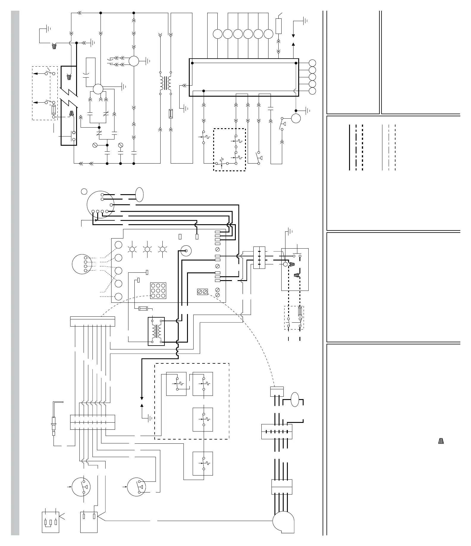
Typical Wiring Diagram
7
1
4
2
5
6
3
8
9
7
1
4
2
5
6
3
8
0
BL
Y
BR
PR
R
R
9
7
1
4
2
5
6
3
8
9
G
R/W
PR
BR
R
R/W
G
MRLCLC MRLC
MRLC
R
R
Overtemperature Switches
(3-Maximum)
Main Limit
Control
NPC
G
PR
Vent System
Pressure Switch
Drain System
Pressure Switch
NPC
BLMV BL
Y
G
MV
GND
GND
M
P
C
1
2
3
BL
Y
Honeywell
Gas Valve
White
Rogers
C RY WG
G Y W R
G Y W R
TH
LT
OK
LT
FLAME
LT
PWR
24 VAC
24 VAC
Y
CT
X
2.0 AMP
Slowblow
Fuse
FU
P1
Integrated
Furnace Control
M2
M1
Heat/Cool
Fan
Cool
Heat
EACEAC L1Neutrals
R
BL
Y
BK BR
BR
M-HI
M-LO
LO
HI
IBM
COM
RC
IBM
BK
W
XFWR-PR1
W
W
W
32 41
32 41
4-Pin Connector P-8
G
G
FU
B K
PBS (Blower Door Switch)
Junction Box
N
H
DISC
To 115/1/60
Power Supply
G
W
BK
G
GND
3
2
4
3
4
1
6
5
3
2
4
1
6
5
3
4
6
5
3
4
6
5
BK
W
BR/W
BK
W
BR/W
BR/W
BR/W
RCIDM
6-Pin
Connector
P-4
2-Pin
Connector
P-2
IDM
4-Pin
Connector
P-9
P-2
9-Pin
Connector
P-1
Flame Sensor
9-Pin
Connector
P-5
GND
SE
To CC
Unused Motor
Lead(s)
3
2.0 AMP
Slowblow Fuse
CT
FU
GND
LC
MRLC MRLC
MRLC
P5-8 P1-8
P5-3 P1-3
P5-6 P1-6
P5-5
P1-4
P1-5
GVR
NPC
NPC
CR YW G
GND
MGV
P5-4
BR
FR
HCR
IDR
HUM
GVR
FLMS
GND
SE
P5-7
P1-7
IFC
24 VAC
L1
24 VAC
115 VAC
NEU
COM
P9-4 P2-2P4-4
P8-1
P8-2
NEU
P9-3P4-3P2-1
IDR
GND
NEU
IBM
IDM
GND
GND
P4-5
P9-2
P4-6
P9-1
RC
RC
GND
PBS
M2
HCR
Heat
Fan
FR
HUM
BR
EAC
Heat/Cool
Cool
P8-3
FU
H N
To 115/1/60
Power Supply
DISC or CB
L1
P1-9
Notes:
1. Iffactorywiringofheatingand
coolingspeedsisnotdesirable,
refertospecicationssection
forappropriatespeeds.
2. Connectunusedmotorleadsto
M1and/orM2.
3. Modelswith3speedmotors;
•Blueleadisformediumspeed
•Noyellowleadonmotor
Legend:
ALC Aux.LimitControl(Temp)
BR BlowerRelay
CC CompressorContactor
CT ControlTransformer
DISC DisconnectSwitch
EAC ElectricAirCleaner
FR FanRelay
FLMS FlameSensor
FU Fuse
GND Ground
GVR GasValveRelay
HCR Heat/CoolRelay
HUM HumidierRelay
IBM IndoorBlowerMotor
IDM IndoorDraftMotor
IDR IndoorDraftRelay
IFC IntegratedFurnaceControl
IR IgnitionRelay
LC LimitControl
MGV MainGasValve
MRLC MainResetLimitControl
MV MainValve
NPC NegativePressureControl
PBS PushButtonSwitch
PL Plug
RC RunCapacitor
SE SparkIngitionElectrode
TH Thermostat(H/C)
WireNut
Wiring Information:
LINEVOLTAGE
•Factorystandard
•FactoryOption
•FieldInstalled
LOWVOLTAGE
•Factorystandard
•FactoryOption
•FieldInstalled
REPLACEMENTWIRE
•Mustbethesamesizeandtypeof
insulationasoriginal(105C*Min.)
WARNING
•Cabinetmustbepremanently
groundedandconformtoI.E.C.,
N.E.C,C.E.C,andlocalcodes
Wire Color Codes:
BK Black
BR Brown
BL Blue
G Green
GY Gray
Electrical Wiring Diagram:
•UpowBlowerInducedDraft
•GasFiredForcedAirFurnace
•SingleStageHeat
•SingleStageCool
•DirectSparkIgnition
O Orange
PR Purple
R Red
W White
Y Yellow
 Loading...