✍ NOTE: After inserting the coaxial cable into the AH-
4 top cover, solder the PL-259 connector to the
coaxial cable.
➀ Remove the top cover (Fig. 1).
➁ Install the control cable and coaxial cable (Fig. 1).
➂ Connect and solder the PL-259 connector to the
coaxial cable (Fig. 4).
➃ Connect the control cable to the AH-4 (Fig. 2).
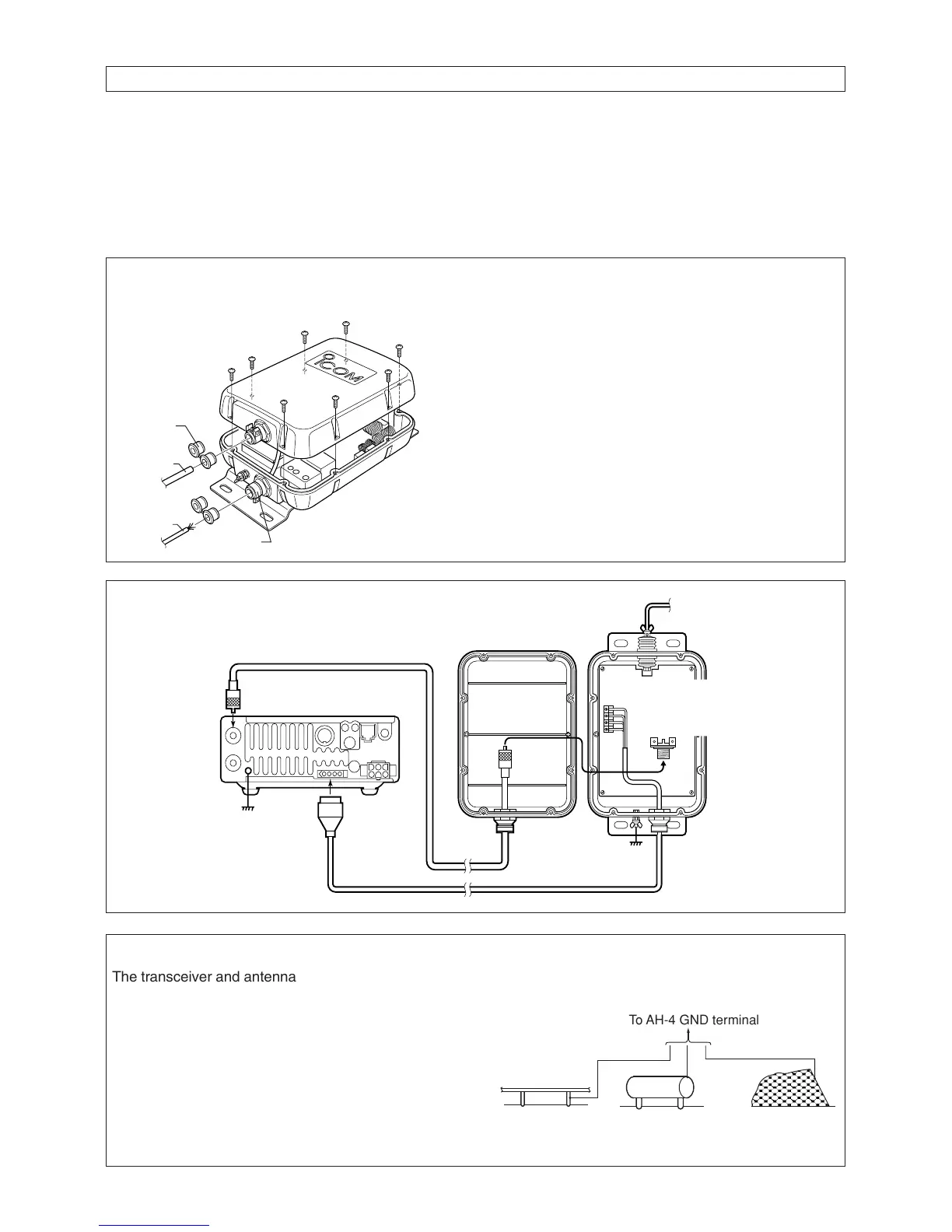
➄ Connect the GND cable to the AH-4 (Fig. 3).
➅ Replace the top cover.
➆ Mount the AH-4 in the desired location; on an an-
tenna pole, in your vehicle’s trunk, etc. (Fig. 5).
➇ Connect an antenna to the AH-4 (Fig. 6).
➈ Connect the control cable and the coaxial cable to
the transceiver.
INSTALLATION
Fig. 1 COVER REMOVAL AND CABLE
INSTALLATION
➀ Remove 8 screws from the top cover and remove
the cover.
➁ Loosen the screws on both cable clamps. If de-
sired, install a strain relief insert (supplied) corre-
sponding to the diameter of the cable.
➂ Install the coaxial cable through the top cover
cable clamp.
➃ Install the control cable through the bottom cover
cable clamp.
➄ After connecting the coaxial cable and control ca-
bles, tighten the cable clamp screws.
The transceiver and antenna tuner must have an ade-
quate ground connection. Otherwise, the overall ef-
fency of the transceiver and antenna tuner installation
will be reduced. Interference, RF feed back and elec-
trical shocks from other equipment could also occur.
For best results, use the heaviest gauge wire or strap
available and make the connection as short as possi-
ble. (see right)
• A long wire connected to the GND terminal as a counter-
poise is also acceptable.
• Ground example

 Loading...


