Do you have a question about the Icom Amateur IC-2200H and is the answer not in the manual?
Select a location supporting the transceiver's weight, avoiding interference with driving and potential injury.
Details on drilling holes, inserting screws, nuts, washers, and adjusting the bracket angle for installation.
Instructions for connecting the transceiver to a 12V DC power source using fuses and terminals.
Guidance on connecting to a 13.8V DC power supply, ensuring proper grounding and fuse capacity.
Tips for selecting a high-quality antenna and a good location for maximum transceiver performance.
Step-by-step guide for installing the PL-259 antenna connector onto the coaxial cable.
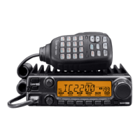
How to connect a microphone to the eight-pin modular socket on the transceiver's front panel.
Recommendations for setting initial volume and squelch levels before powering up the transceiver.
Instructions on using the DIAL to set frequencies and tuning speed preferences.
How to directly enter frequencies using the HM-133V keypad, with an example provided.
Procedure to select minus or plus duplex modes for repeater communication.
Method for setting the subaudible tone to access repeaters, indicated by a musical note symbol.
Guides on using the HM-133V for duplex selection and turning the repeater tone ON.
How to set the desired operating frequency and related settings in VFO mode.
Process for choosing a memory channel using the DIAL after pushing the S.MW MW button.
Steps for programming memory channels using the HM-133V, including frequency and settings.
Instructions on how to program the selected frequency and settings into a memory channel.
| Frequency Range | 144-148 MHz |
|---|---|
| Mode | FM |
| Weight | 1.2 kg |
| Receiver Sensitivity | 0.18 μV (12 dB SINAD) |
| Voltage | 13.8V DC ±15% |
| Antenna Connector | SO-239 |
| Memory Channels | 207 (6 scan edges) |
| Type | Mobile |
| Current drain RX | 1.0A |
| Output Power | 65W, 25W, 10W |
| Current drain TX | 15.0A (max) |