3 - 2
3-2 PLL CIRCUIT
3-2-1 PLL CIRCUIT (MAIN UNIT)
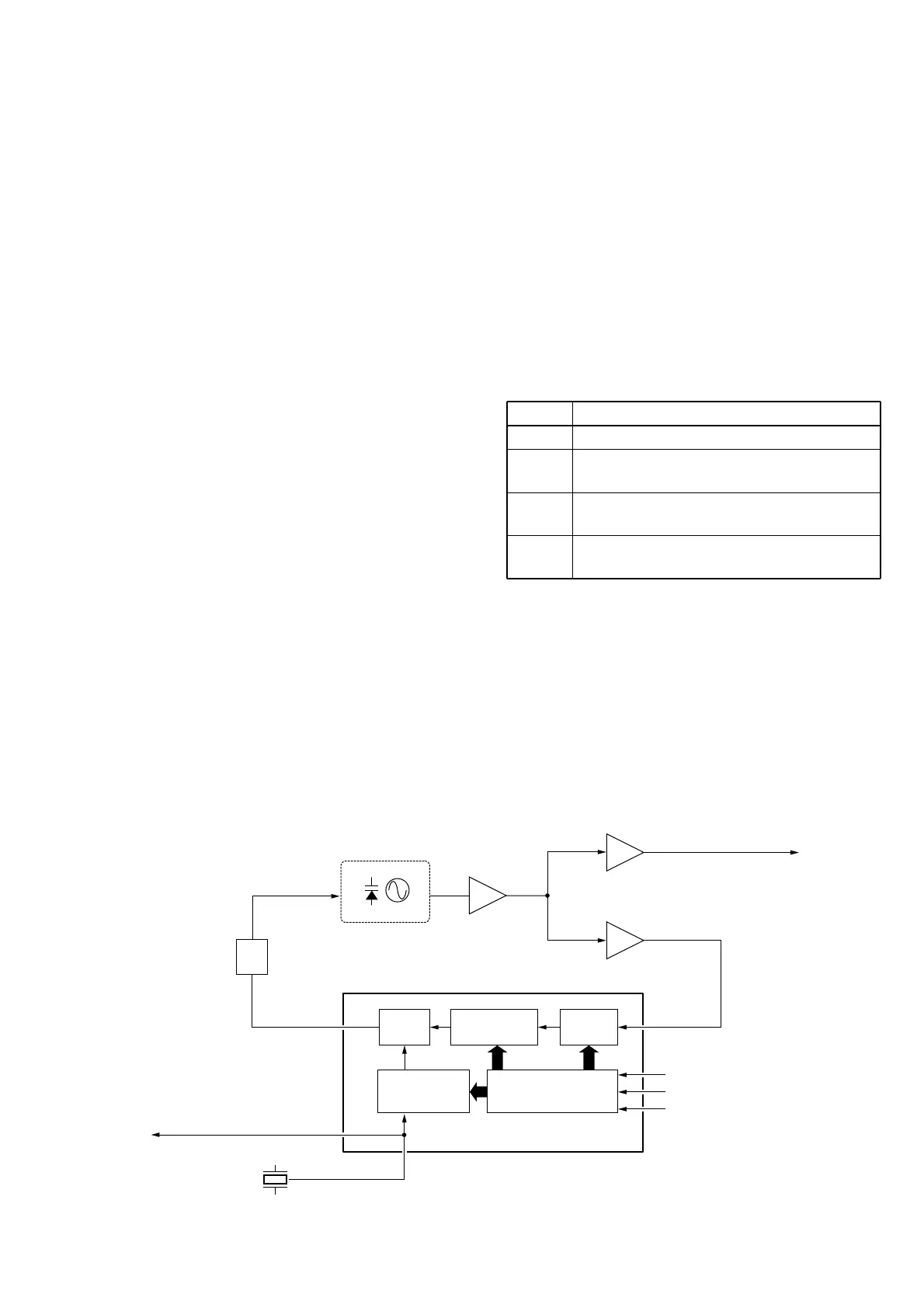
A PLL circuit provides stable oscillation of the receiver 1st
LO frequency. The PLL output compares the phase of the
divided VCO frequency to the reference frequency. The PLL
output frequency is controlled by the divided ratio (N-data) of
a programmable divider.
The PLL IC (IC2) contains a prescaler, programmable
counter, programmable divider phase detector, charge
pomp and etc. The entered signal is divided at the prescaler
and programmable counter section by the N-data ratio from
the CPU. The divided signal is detected on phase at the
phase detector using the reference frequency (21.25 MHz).
If the oscillated signal drifts, its phase changes from that of
the reference frequency, causing a lock voltage change to
compensate for the drift in the oscillated frequency.
3-3 DSC CIRCUITS
3-3-1 DSC DECODE CIRCUIT (MAIN UNIT)
The AF signals from FM IF IC (IC1, pin 9) are filtered at the
bandpass filter (IC3) with +18 dB/octave characteristics to
remove except 1300 Hz and 2100 Hz signals. The filtered
signals are converted analog signals into digital signals at
IC4, and are then applied to the CPU after shaping wave-
form at IC6.
3-3-2 DSC ENCODE CIRCUT (MAIN UNIT)
The DSC signals from the D/A outputs of CPU are amplified
at the buffer amplifier (Q17) and converted into 600 Ω
impedance at T1. The signals are output to the connected
transceiver as floating system output.
3-4 NMEA AND DATA INTERFACE
CIRCUITS
3-4-1 NMEA CIRCUIT (MAIN UNIT)
The NMEA signals (GGA) from OPC-945 are applied to IC5
and are shaped waveform at IC6, and are then applied to
the CPU.
3-4-2 DATA INTERFACE CIRCUIT (MAIN UNIT)
The control signals from the connected transceiver with
OPC-951 are applied to IC8 and are shaped wave form at
IC6, and are then applied to the CPU.
3-5 POWER SUPPLY CIRCUITS
3-5-1 VOLTAGE LINE (MAIN UNIT)
LINE
13.8 V
8 V
5 V
R8V
DESCRIPTION
The voltage from the connected transceiver.
Common 8 V converted from the 13.8 V line and
regulated by the 8 V regulator circuit (IC9).
Common 5 V converted from the 8 V line and
regulated by the 5 V regulator circuit (IC10).
8 V for receiver circuits regulated by the R8V
regulator circuit (Q15, Q16).