Do you have a question about the Icom IC-1271A and is the answer not in the manual?
Detailed specifications for the transmitter section, covering output power and modulation.
Detailed specifications for the receiver section, including intermediate frequencies and sensitivity.
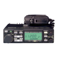
Identification and description of controls and indicators on the front panel of the transceiver.
Identification of connectors and controls located on the rear panel of the unit.
A functional block diagram illustrating the overall circuit structure and signal flow of the transceiver.
Explanation of the circuit responsible for switching between transmit and receive modes in the PA unit.
Description of the RF filter circuits within the RF and RF Mix units.
Detailed description of the Intermediate Frequency (IF) circuitry in the IF unit.
Step-by-step instructions for disassembling the main frame of the transceiver.
Procedures for removing and disassembling the front panel components.
Instructions for disassembling components located on the rear panel of the unit.
Essential safety precautions and preparation steps before performing any maintenance or adjustments.
| Frequency Range | 1240-1300 MHz |
|---|---|
| Mode | SSB, CW, FM |
| IF Rejection | 70 dB |
| Image Rejection | 70 dB |
| Spurious Rejection | 70 dB |
| Power Supply | 13.8 V DC |
| Output Power | 10 W |
| Receiver Sensitivity | 0.25 µV |