SECTION 3 OPTIONAL UNIT INSTALLATION
3 - 1
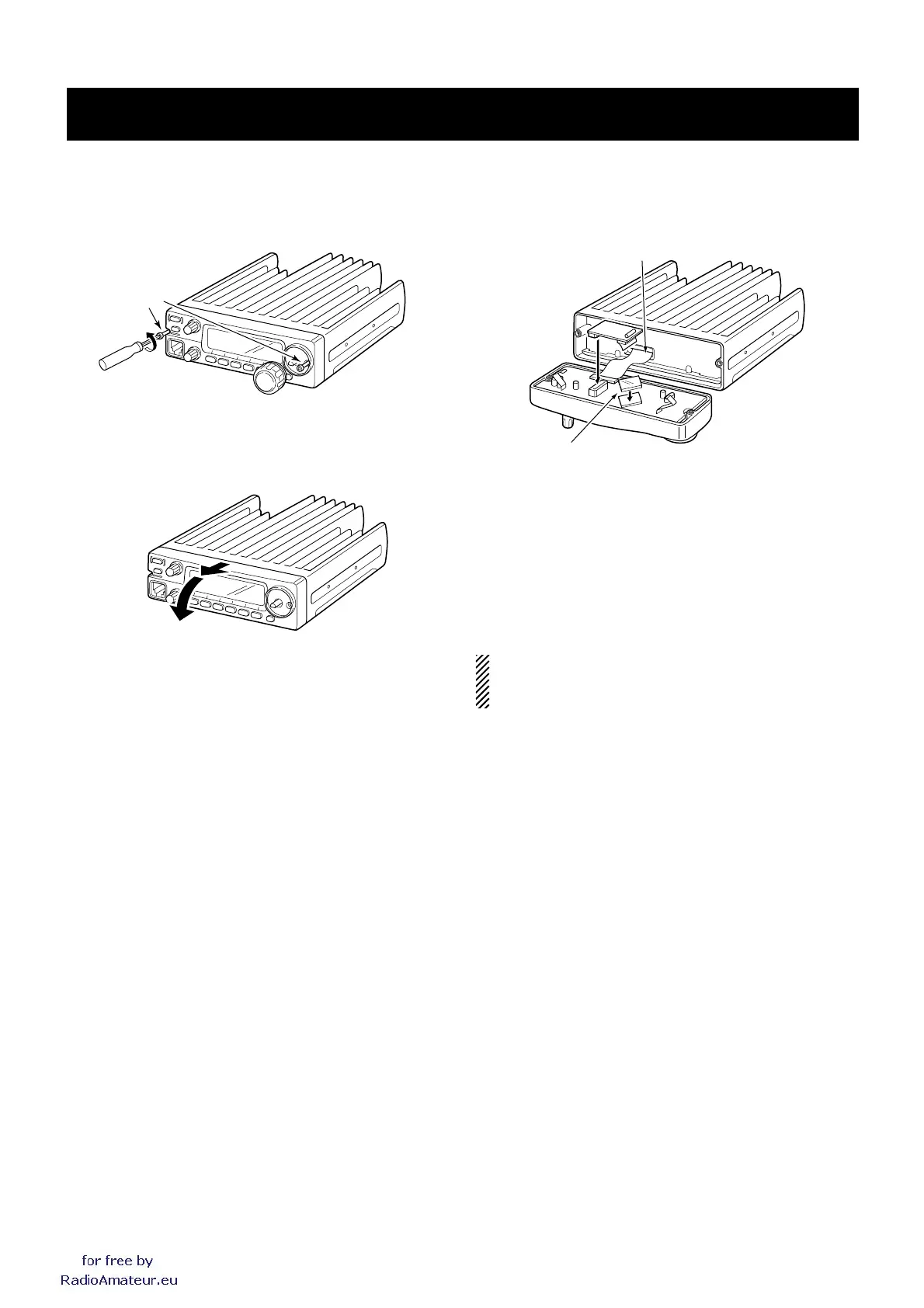
➀ Remove [DIAL] and unscrew the 2 allen-socket bolts from
the front panel using with an allen wrench (2.5 mm;
1
⁄10″).
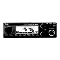
NOTE: When attaching the front panel to the main unit,
make sure the flat cable are running in the groove to pre-
vent catching between front panel and main unit.
➅ Return the front panel and the allen-socket bolts to their
original position.
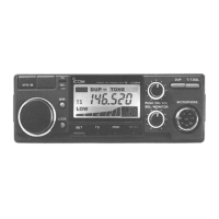
➂ Attach the insulation sheet (supplied as accessory) to IC
on the Front unit.
➃ Remove the protective paper attached to the bottom of
the optional unit to expose the adhesive strip.
➁ Detach the front panel from the main unit.
➄ Intall the unit as illustrated below. Insert tightly to avoid
bad contact.