EasyManua.ls Logo

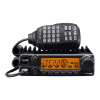
Icom IC-2200H Service Manual

Icom IC-2200H
76 pages
To Next Page IconTo Next Page
Page #1 background imageLoading...
Page #1 background image
VHF TRANSCEIVER
i2200H
SERVICE
MANUAL

Other manuals for Icom IC-2200H

Questions and Answers:

Icom IC-2200H Specifications

General IconGeneral
Frequency Range144-148 MHz
ModeFM
Antenna ConnectorSO-239
Weight1.2 kg
Power Supply Requirement13.8 V DC
Dimensions140 x 40 x 160 mm
Current Consumption15A (at 65W output)
Number of Channels207 (200 regular, 6 scan edges, 1 call)

Summary

SERVICE MANUAL

VHF TRANSCEIVER IC-2200H

Overview of the service manual for the IC-2200H VHF transceiver.

INTRODUCTION

DANGER WARNINGS

Critical safety warnings for operating the transceiver.

ORDERING PARTS

REPAIR NOTES

Essential guidelines for safe and effective transceiver repair.

SECTION 1 SPECIFICATIONS

GENERAL AND TRANSMITTER SPECIFICATIONS

Detailed electrical and performance specifications for the transceiver.

RECEIVER SPECIFICATIONS

Performance metrics for the transceiver's receiver section.

UT-115 SPECIFICATIONS

SECTION 2 INSIDE VIEWS

IC-2200H INTERNAL VIEWS

Top and bottom views of the IC-2200H main unit components.

HM-133V INTERNAL VIEWS

Component layout for the HM-133V microphone.

SECTION 4 CIRCUIT DESCRIPTION

RECEIVER CIRCUITS

Detailed explanation of the transceiver's receiver circuitry.

TRANSMITTER CIRCUITS

Detailed explanation of the transceiver's transmitter circuitry.

SECTION 5 ADJUSTMENT PROCEDURES

SOFTWARE ADJUSTMENTS

Procedures for adjusting frequency, power, deviation, and sensitivity.

SECTION 6 PARTS LIST

SECTION 10 BLOCK DIAGRAMS

SECTION 11 VOLTAGE DIAGRAMS

SERVICE MANUAL ADDENDUM

ADJUSTMENT PROCEDURES

FREQUENCY AND TRANSMIT ADJUSTMENTS

Step-by-step guide for frequency and transmit power adjustments.

RECEIVE ADJUSTMENTS

Step-by-step guide for receiver sensitivity and squelch adjustments.

Related product manuals