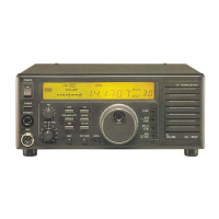
Picture 3: diode is right next to the L601
3. Now replace this diode by a 33pF ceramic capacity (N470). The one leg to the upper solder pad where the diode was, the
other to ground. Ground can be easily found at the metal shielding.
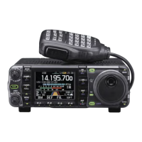
4. As you know, the radio gets very hot just by receiving because the fan does not work if you do not transmit. The fan
should run all the time. This can be done by simply inserting a 100Ohm resistor (or two 56Ohm, ¼ Watt in serie) between
the red fan wire and the top of the inductivity as shown in picture 4. The fan runs now very slowly all the time.
5. You may now let the radio run for about 20minutes. Tune to 50MHz and check the frequency by transmitting. If the
frequency does not match, adjust it by tuning carefully with L601.
This modification has been done on several radios. It always worked very good but I cannot give a guarantee. I am not
responsible for any damages on your radio.
 Loading...