EasyManua.ls Logo

Icom IC-703 - Service Manual

Icom IC-703
77 pages
Print Icon
To Next Page IconTo Next Page
Loading...
HF/ 50MHz ALL MODE TRANSCEIVER
i703
SERVICE
MANUAL

Table of Contents

Other manuals for Icom IC-703

Questions and Answers

  • J
    Jessica GarzaJul 26, 2025
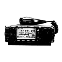
    How to fix Icom IC-703 Transceiver when power does not come on?
    • E
      eleeJul 26, 2025
      If your Icom Transceiver isn't powering on, the DC power cable might not be properly connected, or the fuse could be blown. Also, if you're using a 12V battery, it might be exhausted. Reconnect the power cable correctly and check the battery voltage with the [POWER] pushed IN. Inspect the fuse (located in the DC power cable and the PA unit) and replace it if necessary.
  • B
    Bradley RamirezAug 9, 2025
    What to do if no sound comes from the Icom IC-703 speaker?
    • L
      Lisa ShortAug 9, 2025
      If no sound is coming from the Icom Transceiver speaker, first, try rotating the [AF] knob clockwise to adjust the volume to a comfortable listening level. If that doesn't work, rotate the [SQL] knob counterclockwise to open the squelch. Ensure that the transceiver is not in transmitting mode by releasing the [PTT] button on the microphone. Lastly, verify the connection of any external speakers or headphones.

Summary

Section 1 Specifications

General, Receiver, and Transmitter Specifications

Details operational parameters including frequency coverage, power, sensitivity, and dimensions.

Section 3 Circuit Description

Receiver Circuit Details

Explains the RF, IF, mixer, and demodulator circuits of the receiver.

Transmitter Circuit Details

Details the microphone amplifier, modulator, and RF output stages.

PLL Circuit Details

Describes the Phase-Locked Loop circuits for frequency generation.

Antenna Tuner Circuit Details

Explains the antenna matching network and SWR detection circuits.

Power Supply Circuit Details

Details the voltage regulation and distribution across units.

Section 4 Adjustment Procedures

PLL Adjustments

Procedures for adjusting reference frequency and VCO lock voltages.

Transmitter Adjustments

Calibration steps for transmit peak power, carrier suppression, and output.

Receiver Adjustments

Calibration steps for receiver peak output and noise blanker.

Set Mode Adjustments (No.1)

Configuration settings for S-meter, filter calibration, and power meter.

PA Unit Adjustments

Adjustment procedures for PA unit's idling current and SWR detection.

Set Mode Adjustments (No.2)

Configuration settings for antenna tuner and tuner relay.

Section 7 Semi-Conductor Information

Section 8 Board Layouts

Section 9 Block Diagram

Section 10 Wiring Diagrams

Section 11 Voltage Diagrams

Icom IC-703 Specifications

General IconGeneral
Frequency Range RX0.03-60 MHz
ModesSSB, CW, AM, FM
Impedance50 Ohms
Power Output10 W
Voltage13.8V DC
Current Consumption TX2.5 A
Current Drain RX0.5 A

Related product manuals