3 - 8
3-4-2 OUTPUT POWER DETECTING CIRCUIT
(PA UNIT)
The output power from the power amplifier (Q200, Q201) is
divided at the C640 and C641. The divided voltage is
applied to the power detecting circuit (D640) as detecting
voltage. The detected voltage is applied to the main CPU
(MAIN unit; IC5901) via the A/D convertor (MAIN unit;
IC5601) as “TPZL” signal after being passed through the
switch circuit (IC641, Q646).
3-4-3 IMPEDANCE DETECTING CIRCUIT
(PA UNIT)
The output power from the power amplifier (Q200, Q201) is
applied to the RL640. The signal is applied to the power
detector (D640), and is then applied to the main CPU (MAIN
unit; IC5901) as the reference voltage. The voltage is also
used for power detecting voltage when the antenna tuning is
ON.
The attenuator’s output voltage is depended on the condi-
tion between power amplifier’s output impedance and the
antenna (For example, the voltage becomes high when the
impedance is high, the votage becomes low when the
impedance is low). The voltage is amplified at the Q641, and
is then detected at the impedance detector (D646). The sig-
nal is applied to the main CPU (MAIN unit; IC5901) to ana-
lyze whether the impedance is more than 1.1 or not.
3-4-4 PHASE DETECTING CIRCUIT (PA UNIT)
The phase detecting circuit is composed D643, L640 and
L641.
The input side signal passes through the C646 to shift the its
phase for +90 degrees. The signal is applied to the phase
detecting circuit (L640).
The output side signal is applied to the amplifiers (Q643,
Q811). The amplified signal is applied to the phase detect-
ing circuit (L641).
The detected signal is applied to the comparator circuit
(IC640, pin 2), and is then applied to the main CPU (MAIN
unit; IC5901, pin 75) via the “TPHK” signal.
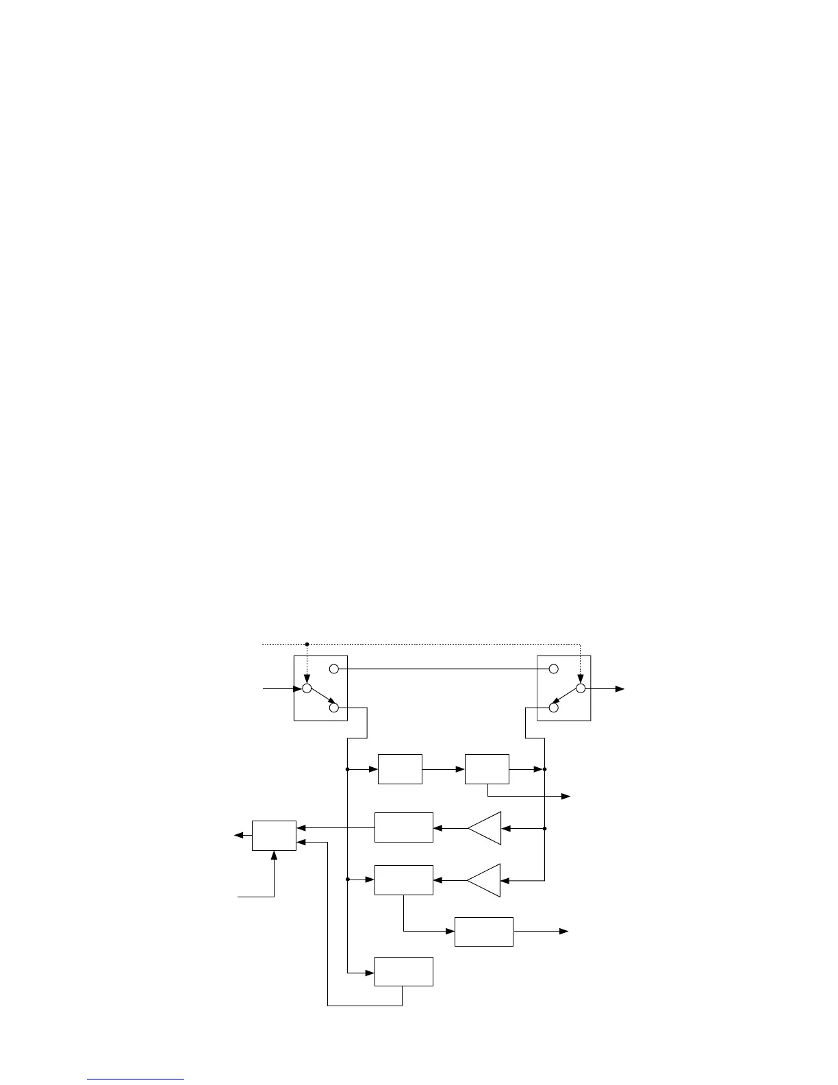
3-4-5 SWR DETECTING CIRCUIT (PA UNIT)
The SWR detecting circuit employs return loss bridge circuit
(L642, R662–R665) which is also composed as 6 dB atten-
uator (input-output impedance is 50 Ω).
The output power from the power amplifier (Q200, Q201)
passes through the attenuator, and is then applied to the
SWR detecting circuit (D645). The signal is applied to the
main CPU (MAIN unit; IC5901) via the A/D convertor (MAIN
unit; IC5601) as “TSWL” signal.
The main CPU is analyzed SWR to use the “TSWL” signal
from the SWL detecting circuit and “TPZL” signal from the
power detecting circuit.
ATT
to the antena
RL640 RL641
D645
D643
D640
D646
Q641
IC640
IC641
Q646
Q643
Q811
Switch
SWR
detector
Impedance
detector
Phase
detector
Power
detector
Comparator
Amp.
Amp.
"TPZL" signal to the A/D
convertor
(MAIN unit; IC5601, pin 15)
"TPZS" signal to the main
CPU
(MAIN unit; IC5901, pin 74)
The signal from the
power/SWR detector
(D560, D561)
"TDTS" signal from the
main CPU
(MAIN unit; IC5901, pin 44)
"TSWL" signal to the A/D
convertor
(MAIN unit; IC5601, pin 2)
"TPHK" signal to the main
CPU
(MAIN unit; IC5901, pin 75)