3 - 6
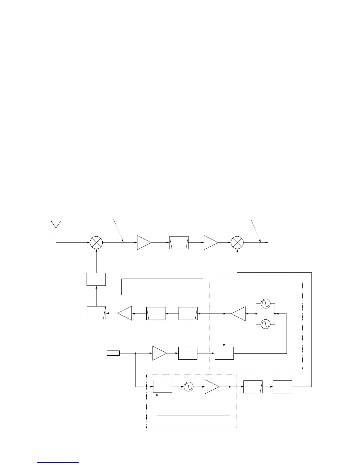
When the “FORL” voltage exceeds the “POCV” voltage, ALC
bias voltage from IC2701 (pin 1) controls 1st and 2nd IF
amplifiers (Q831, Q1401). This adjusts the output power to
the level determined by the RF power setting until the
“FORL” and “POCV” voltages are equalized.
In AM mode, IC2701 operates as an averaging ALC amplifi-
er with Q2703. Q2703 turns ON and the “POCV” voltage is
shifted for 4 W AM output power.
The ALC bias voltage from IC2701 is also applied to the
main CPU (IC5901) via the A/D converter (IC5601) as the
“ALCL” voltage for ALC meter indication.
An external ALC input (minus voltage) from the [ACC] sock-
et (pin 6) is shifted to plus voltage at D2781 and is applied
to the buffer amplifier (Q2781). External ALC operation is
identical to that of the internal ALC.
3-2-8 APC CIRCUIT (MAIN UNIT)
The APC (Automatic Power Control) circuit protects the
power amplifiers on the PA unit from high SWR and exces-
sive current for the HF/50 MHz band.
The reflected wave signal appears and increases on the
antenna connector when the antenna is mismatched. The
HF/50 MHz reflected signal level is detected at D561 (PA
unit), and is amplified at the APC amplifier (IC2701) and
applied to the ALC circuit as the reference voltage.
For the current APC, the driving current at the power ampli-
fier is detected in the voltages (“IDH” and “IDL”) which
appear at both terminals of a 0.012 Ω resistor (R216) on the
PA unit. The detected voltages are applied to the differential
amplifier (IC2701, pins 9, 10). When the current of the power
amplifier exceeds allowed current, IC2701 controls the ALC
line via IC2701 to prevent excessive current flow.
3-2-9 RF, ALC, SWR METER CIRCUITS
(MAIN UNIT)
While transmitting, RF, ALC or SWR meter readings are
available and can be selected with the [MET] switch.
(1) Power meter
The “FORL” voltage is applied to the main CPU (IC5901) via
the A/D converter (IC5601, pin 12) for indicating the output
power.