MAINTENANCE
AND
ADJUSTMENT
8
8-1
DISASSEMBLING
THE
TRANSCEIVER
Follow
the
transceiver disassembly procedures
shown here
when you want
to
install an option or replace
a
component.
CAUTION: DISCONNECT the DC power cable
from
the transceiver before performing any
work
on the transceiver.
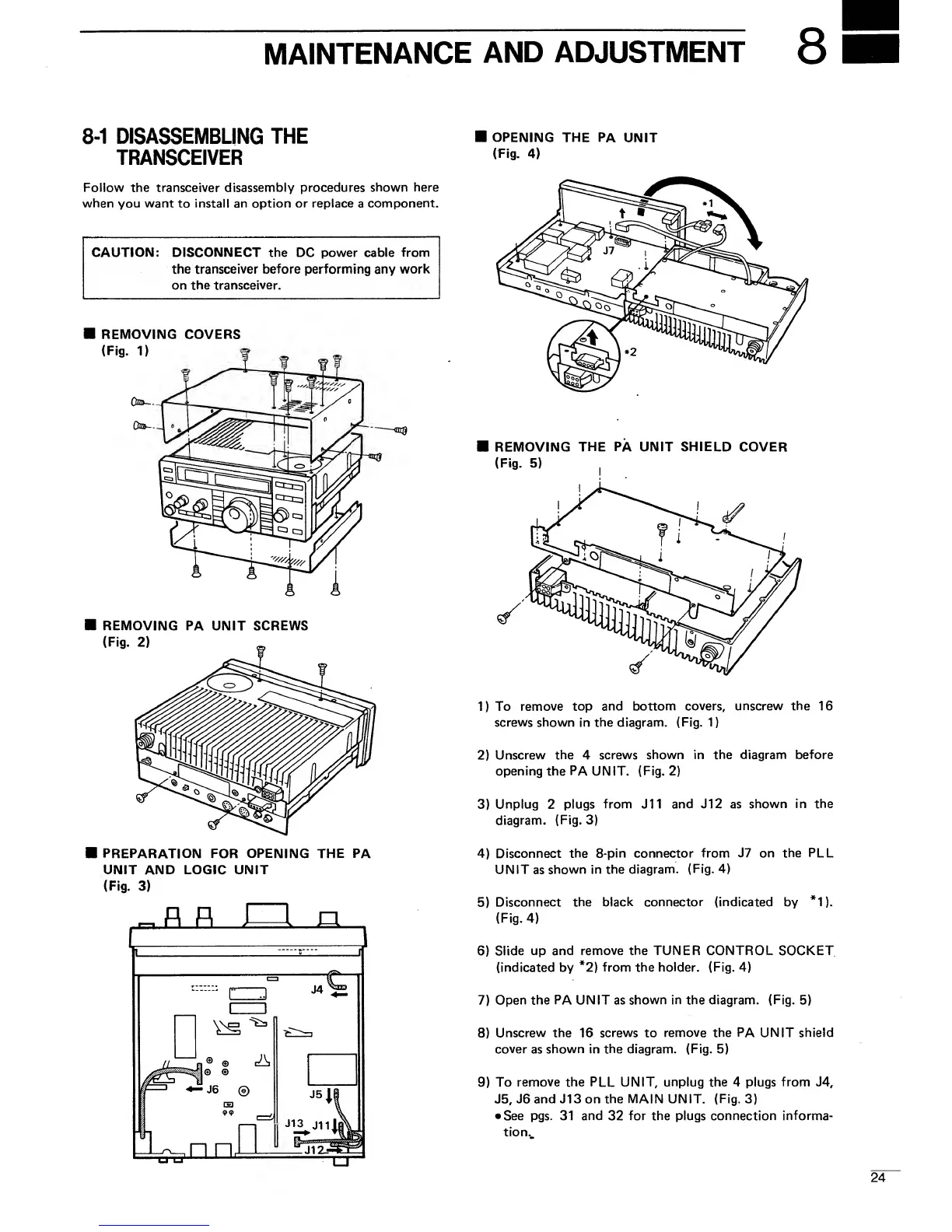
REMOVING COVERS
(Fig.
1)
REMOVING PA
UNIT SCREWS
(Fig.
2)
PREPARATION
FOR
OPENING THE PA
UNIT AND LOGIC UNIT
(Fig.
3)
r
r
J—
I n
OPENING
THE PA
UNIT
(Fig.
4)
REMOVING
THE PA UNIT
SHIELD
COVER
(Fig.
5)
1)
To
remove top and
bottom covers, unscrew
the
16
screws shown in the diagram.
(Fig.
1
)
2)
Unscrew the
4
screws
shown in the diagram
before
opening the PA UNIT.
(Fig.
2)
3)
Unplug
2
plugs
from
J11
and J12 as
shown in the
diagram.
(Fig.
3)
4)
Disconnect
the 8-pin connector
from J7 on the PLL
UNIT
as
shown
in the
diagram.
(Fig.
4)
5)
Disconnect
the black connector (indicated by
*1).
(Fig.
4)
6)
Slide
up and remove
the
TUNER CONTROL SOCKET
(indicated
by
*2)
from
the
holder. (Fig.
4)
7)
Open the
PA
UNIT as
shown in the diagram. (Fig.
5)
8)
Unscrew the 16
screws
to
remove the PA UNIT shield
cover
as
shown in the diagram.
(Fig.
5)
9)
To
remove
the PLL UNIT,
unplug
the 4 plugs
from J4,
J5,
J6 and J13 on the MAIN UNIT.
(Fig.
3)
•
See
pgs.
31 and
32
for the plugs connection informa-
tion.

 Loading...


