3
MAINTENANCE
AND
ADJUSTMENT
8-7
ADJUSTMENTS
Your
IC-725
has been thoroughly adjusted and
checked
at
the
factory before
being shipped.
All
adjustable
trimmers
and
coils
should
be
adjusted
by
an
authorized
Icom
Dealer
or
Service
Center.
Your
transceiver
warranty
does
not
cover
problems
caused
by
unauthorized
internal
adjustments.
(1)
MAIN
DIAL BRAKE
ADJUSTMENT
The
tension of the
MAIN
DIAL
may
be
adjusted
to
suit
your
operating
requirements.
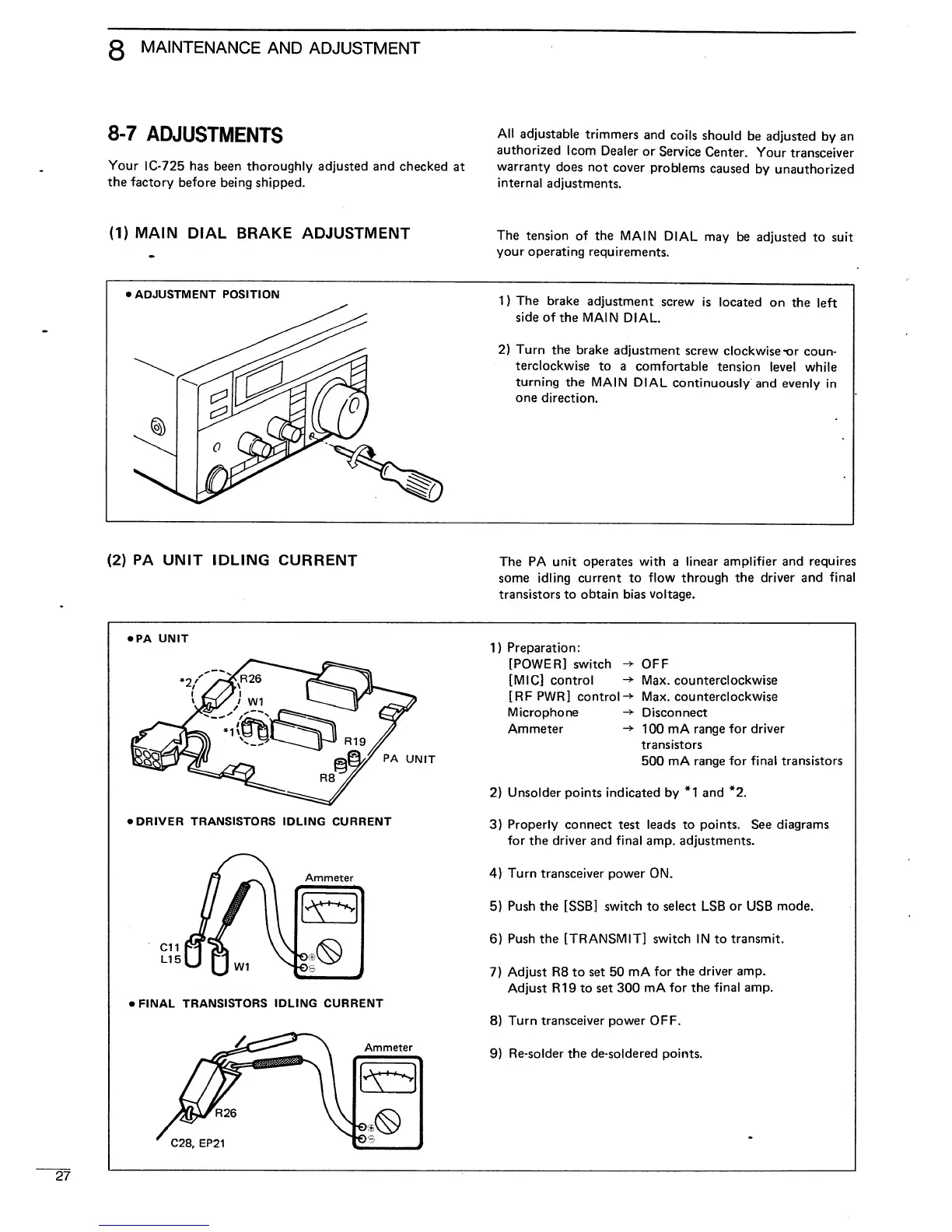
•
ADJUSTMENT POSITION
1
)
The
brake
adjustment
screw
is
located
on
the
left
side of
the MAIN
DIAL.
2)
Turn
the
brake
adjustment
screw
clockwise
-or
coun-
terclockwise
to a
comfortable
tension
level
while
turning
the
MAIN
DIAL
continuously
and evenly
in
one
direction.
(2)
PA
UNIT IDLING
CURRENT
The PA unit operates with
a
linear amplifier and
requires
some
idling current
to
flow through
the driver and
final
transistors to obtain bias
voltage.
»PA UNIT
PA
UNIT
•
DRIVER TRANSISTORS
IDLING CURRENT
Ammeter
>
FINAL
TRANSISTORS
IDLING CURRENT
Ammeter
1)
Preparation:
[POWER] switch
->
OFF
[MIC] control
-+
Max. counterclockwise
[RF PWR] control-*
Max.
counterclockwise
Microphone
-»
Disconnect
Ammeter
100 mA range
for driver
transistors
500 mA
range for final transistors
2)
Unsolder points indicated by
*1
and
*2.
3)
Properly
connect test leads to points. See diagrams
for the
driver
and final amp. adjustments.
4)
Turn transceiver power
ON.
5)
Push the [SSB] switch
to
select LSB or USB
mode.
6)
Push the [TRANSMIT] switch IN to transmit.
7)
Adjust R8 to set 50 mA
for
the
driver amp.
Adjust R19 to set
300 mA
for the
final amp.
8)
Turn transceiver power OFF.
9)
Re-solder the de-soldered points.
C28, EP21

 Loading...


