1
CONTROL
FUNCTIONS
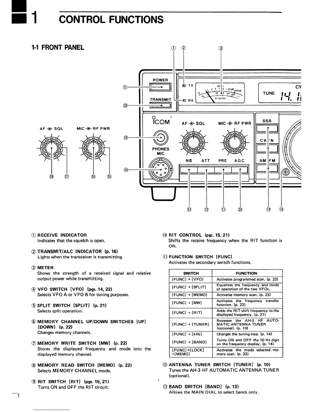
1-1
FRONT PANEL
(D
<D
AF-§>-SQL
MIC
-§>-
RF
PWR
(D
RECEIVE
INDICATOR
Indicates
that the
squelch
is open.
(D
TRANSMIT/ALC INDICATOR
(p.
16)
Lights
when
the
transceiver
is transmitting.
©
METER
Shows
the
strength
of
a
received
signal and relative
output power
while transmitting.
@
VFO SWITCH
[VFO]
(pgs.
14,
22)
Selects
VFO
A
or
VFO
B
for tuning
purposes.
©SPLIT
SWITCH [SPLIT]
(p.
21)
Selects
split operation.
©
MEMORY
CHANNEL
UP/DOWN
SWITCHES [UP]
[DOWN]
(p.
22)
Changes
memory channels.
(7)
MEMORY WRITE
SWITCH
[MW]
(p.
22)
Stores
the
displayed
frequency
and mode into the
displayed
memory channel.
®
MEMORY
READ
SWITCH [MEMO]
(p.
22)
Selects MEMORY CHANNEL mode.
©RIT
SWITCH [RIT] (pgs.
15,21)
Turns
ON
and OFF the RIT circuit.
>
RIT CONTROL
(pgs.
15,21)
Shifts the
receive frequency
when
the RIT function is
ON.
)
FUNCTION
SWITCH
[FUNC]
Activates the secondary switch functions.
SWITCH FUNCTION
[FUNC]
+
[VFO] Activates programmed
scan.
(p.
23)
[FUNC]
+
[SPLIT]
Equalizes
the
frequency and mode
of operation
of the
two
VFOs.
[FUNC]
+
[MEMO] Activates
memory scan.
(p.
23)
[FUNC]
+
[MW]
Activates
the
frequency transfer
function,
(p.
22)
[FUNC]
+
[RIT]
Adds
the
RIT
shift frequency to
the
displayed frequency,
(p.
21
)
[FUNC]
+
[TUNER]
Bypasses the AH-3
HF AUTO-
MATIC ANTENNA
TUNER
(optional),
(p.
10)
[FUNC]
+
[kHz]
[FUNC]
+
[BAND]
Changes the tuning step.
(p.
14)
Turns ON
and OFF the
10
Hz digit
on the frequency display,
(p.
14)
[FUNC]
+[
LOCK]
+[MEMO]
Activates
the mode
selected me-
mory
scan.
(p.
23)
©
ANTENNA TUNER SWITCH
[TUNER]
(p.
10)
Tunes the AH-3 HF AUTOMATIC
ANTENNA
TUNER
(optional).
(0)
BAND SWITCH [BAND]
(p.
13)
Allows the MAIN DIAL to select
bands only.

 Loading...