BFO
FREQUENCY IN EACH MODE
MODE
FREQUENCY (MHz)
USB
9.0130
CW(Tx)
9.0106
LSB
9.0100
CW
(Rx)
9.0098
AM
NO
OUTPUT
4-1-10
AF AMP CIRCUIT
(MAIN UNIT)
The AF signal from the
AF
input mode selector
switch is
applied to the AF
preamplifier
(Q35,
Q36).
The CW
sidetone
signal is applied
to Q36.
The output from the AF preamplifier is applied
to
the [AF]
control (FRONT UNIT, R1
b)
and the 2.8 kHz cut-off active
low-pass filter
(Q37).
The AF signal is power-amplified
at
IC9 to drive the speaker.
4-1-8
DEMODULATOR CIRCUITS
(MAIN UNIT)
The IC-725
has 2 detector
circuits, a product
detector
and
a diode
detector to
demodulate the SSB, CW signal and
AM signal
respectively.
In SSB
or CW mode,
the 2nd
IF signal
from the IF amplifier
(Q29)
is
mixed with
the BFO signal at the product
detector
(ICS) to demodulate the 2nd IF signal into
an
AF signal.
The detected signal passes through
the AF input mode
selector
switch (ICS).
In AM
mode, the 2nd
IF signal from
029
passed through
Cl
21 is detected at D62
and passes through the AF input
mode
selector switch (ICS).
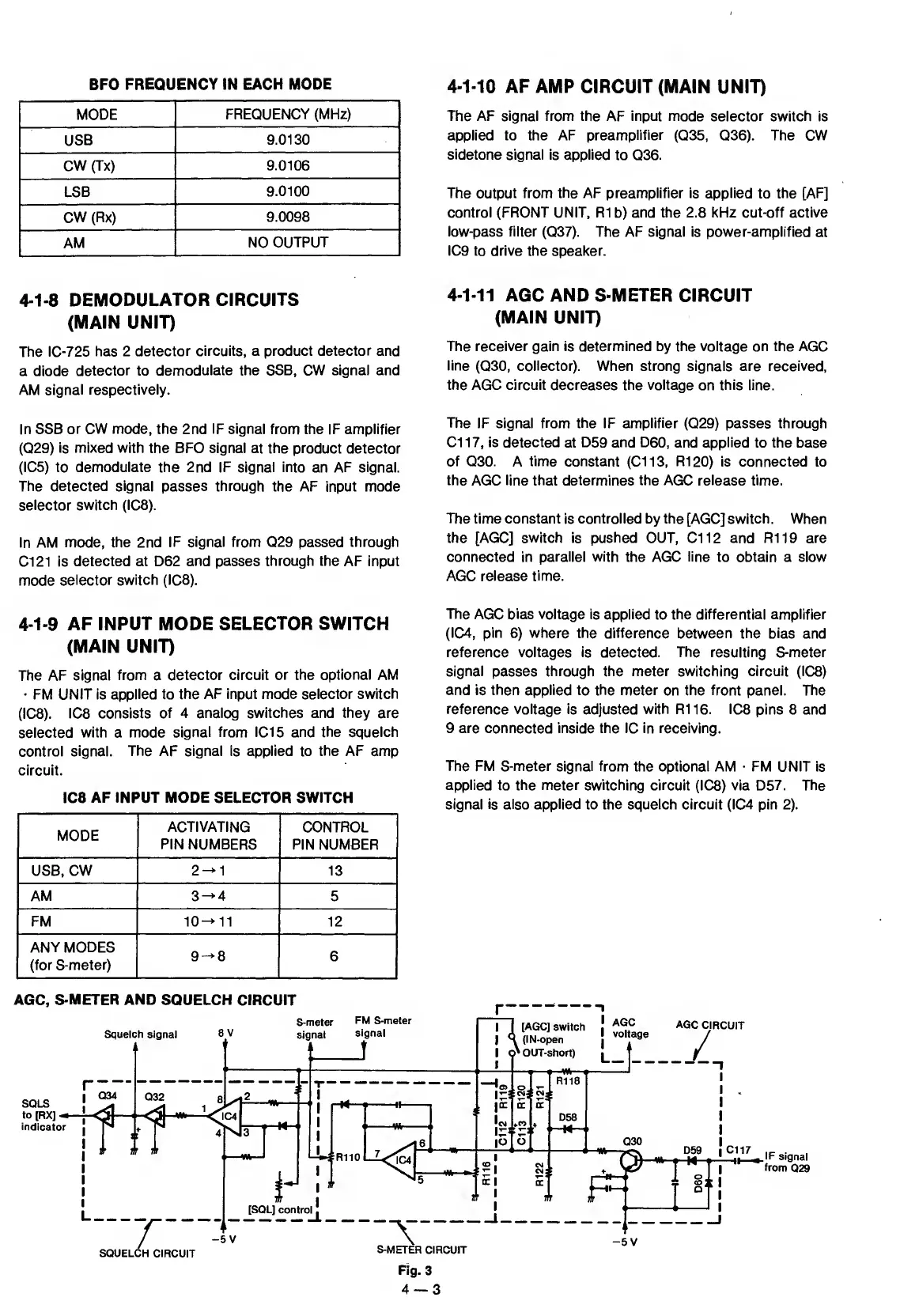
4-1-11
AGC
AND S-METER CIRCUIT
(MAIN UNIT)
The receiver gain is determined by the voltage on the AGC
line
(030,
collector). When strong signals are received,
the AGC circuit decreases the voltage
on
this line.
The
IF signal
from the
IF
amplifier
(029)
passes through
Cl 1
7,
is detected
at
D59 and D60,
and
applied
to the base
of 030.
A
time constant (Cl
13,
R120)
is connected to
the AGC line that determines the AGC release time.
The
time constant is controlled by the [AGC] switch. When
the
[AGC]
switch is
pushed OUT, Cl
12
and R119 are
connected
in
parallel with
the AGC
line
to obtain a slow
AGC
release time.
4-1-9
AF INPUT MODE SELECTOR SWITCH
(MAIN UNIT)
The
AF signal
from
a
detector circuit
or
the
optional
AM
•
FM UNIT is
applied
to
the AF input mode selector switch
(ICS).
ICS consists
of 4 analog switches and they are
selected
with a mode signal
from IC15 and the squelch
control signal.
The AF signal is applied to the AF amp
circuit.
ICS
AF INPUT MODE SELECTOR SWITCH
MODE
ACTIVATING
PIN NUMBERS
CONTROL
PIN
NUMBER
USB, CW
2-^1
13
AM
3^4
5
FM
10-^11
12
ANY MODES
(for S-meter)
9->8
6
The
AGC
bias voltage
is applied to the differential amplifier
(IC4, pin
6)
where the difference between the bias and
reference voltages is detected. The resulting S-meter
signal
passes
through the meter switching circuit (ICS)
and is then applied to the meter
on the
front
panel. The
reference voltage is
adjusted
with R116. ICS
pins 8 and
9 are connected inside the
1C
in receiving.
The FM S-meter signal from
the optional AM
•
FM UNIT is
applied
to
the meter switching circuit
(ICS) via D57. The
signal is also
applied
to the squelch circuit (IC4 pin
2).