EasyManuals Logo

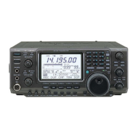
Icom IC-7400 Service Manual

Icom IC-7400
84 pages
To Next Page IconTo Next Page
To Previous Page IconTo Previous Page
Page #5 background imageLoading...
Page #5 background image
2 - 1
SECTION 2
.
INSIDE VIEWS
* Located under
side of the point
1st LO PLL circuit
PLL IC
(IC1801: MC145170)
2nd LO and reference
oscillator circuit
1st mixer circuit
(Q211, Q212: 2SK1740)
3rd LO PLL circuit
2nd mixer
(D261: HSB88WS)
RF unit
TX 3rd mixer
(IC400: MC1496V)
DSP unit
RX 3rd mixer *
(IC280: TC4W53F)
MAIN unit
MAIN AND RF UNITS

Other manuals for Icom IC-7400

Questions and Answers:

Question and Answer IconNeed help?

Do you have a question about the Icom IC-7400 and is the answer not in the manual?

Icom IC-7400 Specifications

General IconGeneral
Frequency Range TX1.8-54 MHz
Frequency Range RX0.03-60 MHz
ModesSSB, CW, RTTY, AM, FM
Output Power100W (HF/50MHz), 50W (144MHz)
Receiver TypeTriple conversion superheterodyne
Antenna ConnectorSO-239
IF RejectionMore than 70 dB
Supply Voltage13.8 V DC ±15%
Current Drain RX1.5 A
Image RejectionMore than 70 dB
Audio Output Power2 W
Current Drain TX20 A
Sensitivity0.13 μV (SSB/CW)
SelectivitySSB: 2.4 kHz

Related product manuals