3. Circuit Modifications
No modifications are required to the standard circuit. The XRef is simply connected to several
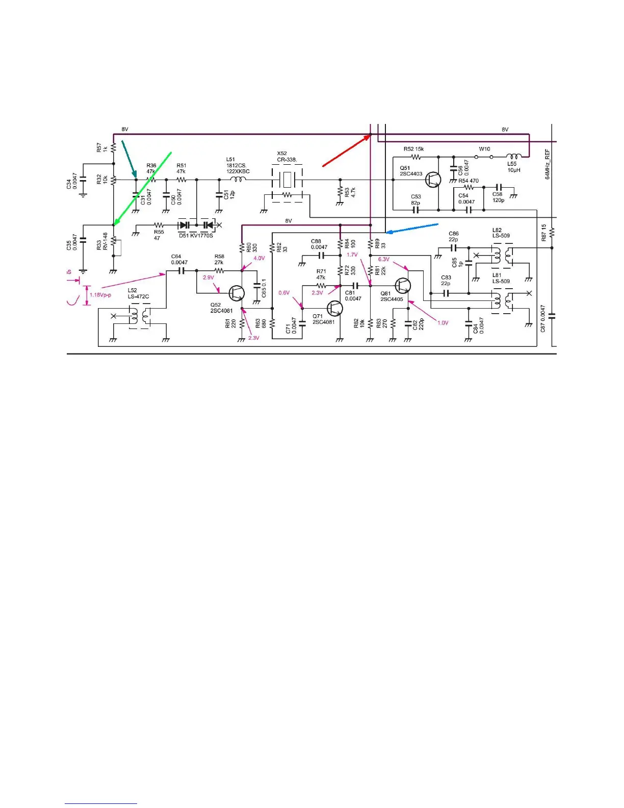
points on the PLL board. An extract from the circuit diagram in Figure 1 shows where
connections are to be made.
Figure 1. – Icom IC-756ProIII Reference Oscillator Circuit
The Blue arrow indicates where the output of the Reference Oscillator is sampled.
The Green arrows indicate where the control voltage is fed back to the Reference Oscillator.
The Red arrow indicates where +8V is taken to power the XRef.
4. Installation
For this installation, you will need about 300mm of very thin coax - say RG178B or RG316 and
a socket to suit. As well, a small signal NPN transistor is needed (e.g. BC547/8/9). You will also
need some short lengths of very fine gauge hookup wire and a small piece of double-sided
foam adhesive tape.
Remove the bottom cover of the radio.
A photo of the PLL board, taken from the Service Manual, is shown in Figure 2. Locate the
Reference Oscillator area in the top right corner of the PLL board.

 Loading...


