EasyManua.ls Logo

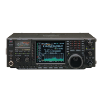
Icom IC-756PROII Service Manual

Icom IC-756PROII
118 pages
To Next Page IconTo Next Page
Page #1 background imageLoading...
Page #1 background image
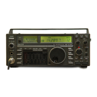
HF/50MHz ALL MODE TRANSCEIVER
SERVICE
MANUAL

Table of Contents

Other manuals for Icom IC-756PROII

Questions and Answers:

Icom IC-756PROII Specifications

General IconGeneral
BrandIcom
ModelIC-756PROII
CategoryTransceiver
LanguageEnglish

Summary

Introduction and Safety

Ordering Replacement Parts

Instructions for ordering replacement parts.

Repair Safety Notes

Important guidelines for performing repairs.

Danger: Electrical and RF Hazards

Warning against incorrect power connections and excessive RF signal.

Section 1: Specifications

General Specifications

Covers frequency coverage, modes, memory channels, connectors, temperature, stability, power supply.

Transmitter Specifications

Details output power, modulation, spurious emissions, carrier suppression, and connector types.

Receiver Specifications

Includes receive system, intermediate frequencies, sensitivity, selectivity, and audio output.

Antenna Tuner Specifications

Covers matching impedance range, minimum operating power, tuning accuracy, and insertion loss.

Section 2: Inside Views

Top View of Transceiver Internals

Identifies major internal components visible from the top.

Bottom View of Transceiver Internals

Identifies major internal components visible from the bottom.

Section 3: Circuit Description

Receiver Circuitry Overview

Explains receiver construction, RF switching, bandpass filters, and pre-amplifiers.

RF Amplifier and 1st Mixer Circuits

Explains the mixing process converting receive signals to the 1st IF.

Noise Blanker and 2nd IF Circuits

Details noise detection, gating, and 2nd IF amplification/filtering.

3rd Mixer and DSP Receiver Circuits

Explains 3rd mixer operation and DSP functions for digital filtering.

Twin PBT, AGC, S-Meter, Squelch, and AF Amplifier Circuits

Describes digital passband tuning, gain control, signal metering, and audio amplification.

Transmitter Circuitry Overview

Details microphone amplifier, VOX, and DSP transmitter circuits.

Speech Compressor and RF Circuits

Explains speech compression, IF amplification, mixing, and RF output stages.

Low-Pass Filter, ALC, and Temperature Protection Circuits

Describes harmonic suppression, level control, and thermal management.

PLL Circuits Overview

Explains PLL unit function, generating LO frequencies for dualwatch and scope.

Antenna Tuner Circuits Overview

Details matching circuit, detectors, motor control, and CPU port allocation.

Scope and Power Supply Circuits

Describes scope receiver operation and power supply distribution.

Logic and Port Allocation Circuits

Details logic circuits for band selection and CPU port assignments.

SECTION 4: Adjustment Procedures

Preparation for Adjustments

Lists required test equipment and necessary connections.

PLL Adjustments

Step-by-step procedures for adjusting PLL circuits.

Transmitter Adjustments

Procedures for calibrating transmitter parameters like output power and gain.

Receiver Adjustments

Procedures for adjusting receiver peak sensitivity, distortion, and mixer balance.

Tuner and Meter Adjustments

Procedures for adjusting the antenna tuner, SWR detector, and meters.

SECTION 5: Parts List

Front Unit Parts

List of mechanical and electrical parts for the front unit.

Display Unit Parts

List of electrical components for the display unit.

Main-A Unit Parts

List of parts for the main-A unit.

DSP-A Board Parts

List of parts for the DSP-A board.

RF-B Unit Parts

List of parts for the RF-B unit.

BPF-A Unit Parts

List of parts for the BPF-A unit.

Preamp Unit Parts

List of parts for the preamp unit.

Tuner-A Unit Parts

List of parts for the tuner-A unit.

Ctrl-A Unit Parts

List of parts for the CTRL-A unit.

Filer-A Unit Parts

List of parts for the filter-A unit.

Chassis Unit Parts

List of parts for the chassis unit.

SECTION 7: Semi-Conductor Information

Transistors and FETs

Electrical schematics and symbols for transistors and FETs.

SECTION 8: Board Layouts

Display Board Layouts

Component layouts for the display board's top and bottom views.

Front Panel Board Layouts

Component layouts for the front panel boards (Mode, Phone, Key, Ten-Key).

Internal Board Layouts

Component layouts for internal boards (Memory, PBT, MIC, RIT).

Main Unit Board Layouts

Component layouts for Main-A and DSP-A units (top and bottom views).

RF-B Unit Board Layouts

Component layouts for the RF-B unit (top and bottom views).

BPF-A and Preamp Board Layouts

Component layouts for BPF-A and Preamp boards (top and bottom views).

PLL Unit Board Layouts

Component layouts for the PLL unit (top and bottom views).

PA Unit Board Layouts

Component layouts for the PA unit (top and bottom views).

Filter-A Unit Board Layouts

Component layouts for the filter-A unit (top and bottom views).

Ctrl-A Unit Board Layouts

Component layouts for the CTRL-A unit (top and bottom views).

Tuner-A Board Layouts

Component layouts for the tuner-A board (top and bottom views).

SECTION 9: Block Diagram

SECTION 10: Voltage Diagrams

Front Unit Voltage Diagram

Voltage distribution diagram for the front unit.

DSP-A Board Voltage Diagram

Voltage distribution diagram for the DSP-A board.

Tuner-A, Memory, and Ctrl-A Unit Voltage Diagrams

Voltage distribution diagrams for tuner-A, memory, and CTRL-A units.

Main-A Unit Voltage Diagrams

Voltage distribution diagrams for the main-A unit.

RF-B Unit Voltage Diagram

Voltage distribution diagram for the RF-B unit.

PLL Unit Voltage Diagram

Voltage distribution diagram for the PLL unit.

PA Unit and Filter-A Unit Voltage Diagrams

Voltage distribution diagrams for the PA and Filter-A units.

Related product manuals